
VCSELs and Flat Optics — A Gamechanger For ToF Applications
By Ludovic Marigo, Product Design/Technical Lead, NIL Technology
Vertical-Cavity Surface-Emitting Lasers (VCSELs) have strong capabilities compared to light emitting diodes (LED) and edge emitting lasers (EEL). VCSELs have high efficiency, better manufacturability, improved testing, and are therefore replacing LEDs and EELs in the consumer, industrial, and automotive applications. The vertical emission and beam profile of VCSELs enable easy integration of flat optics into a compact illumination module. Flat optics can pattern the VCSEL beam profile to include a batwing profile for the diffuser or dot patterns to cover all ranges of Time of Flight (ToF) applications.
Increased Use Of VCSEL And The Need For Flat Optics
iPhone’s successful deployment of 3D facial recognition demonstrated the use of VCSELs for identity authentication in gaining access to buildings as well as sensitive information. Since then, the applications have grown from consumer electronics to applications in automotive, 3D sensing for AR/VR, room-scanning, logistics support, robotic navigation, and robotic end-effector manipulation. The European Union’s mandate for advanced safety systems is driving increased development in driver monitor systems, which include driver drowsiness and driver distraction detection.
In such depth sensing applications, each dot of the VCSEL array is split into several individual dots leading to tens of thousands of dots projected on the object of interest to ensure robust performance. Delivering a uniform array of dots, with no edge artifacts, needs sophisticated optics that are perfectly aligned and robust to environmental stresses. Thanks to Diffractive Optics Elements (DOEs), it is now possible to integrate the collimation and dot projector functions on flat-optics and thus have compact and precisely assembled modules.
Building VCSEL-Based Dot Projectors With Flat Optics
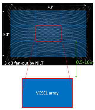
A typical depth sensing application uses 1,800 dots generated from a VCSEL array of 200 emitters. The VCSEL beams need to be collimated and split into multiple dots. A typical fanout (beam splitter) splits each incoming VCSEL emitter beam into equally distributed 3x3 dots. It is critical that the dots are highly uniform and that there are no tiling artifacts between the nine regions. The picture below shows a VCSEL array with hundreds of emitters duplicated nine times to cover a field of illumination (FOI) of 70°x50° and with a dot non-uniformity < 10%.
Assembling Flat Optics On A VCSEL
Flat DOEs (Collimator and Fanout) are easily integrated on top of a VCSEL thanks to the flat glass with a matching aspect ratio of the VCSEL array. Collimator and Fanout can be created on a single active surface, two surfaces where two wafers are stacked on each other, or a single glass wafer with active surfaces on both sides of the same glass. NILT recently demonstrated a combined collimator fanout on a single element, making handling, alignment, and module integration simpler compared to a multi-element module.
Depth Sensing Using Dot Projectors
ToF is now the widely used method for depth sensing over structured light and stereo vision. The distance from the sensor to the object is measured with a periodical signal generated by modulating the VCSEL. Indirect Time of Flight (iToF) is determined by measuring the phase shift in the received signal, while direct Time of Flight (dToF) involves measuring the time between the transmitted and received pulse.
Until recently, the iToF applications used VCSELs driven at low power with a diffuser to detect the presence of objects up to a distance of a couple of meters and their 3D contours. dToF applications, thanks to the very short pulse and high overdrive of the VCSEL sources, enable the depth measurement up to several meters, as needed to scan a room. The primary limitations remain the source modulation and the ability to deliver higher power.
With the development of multi-junction VCSEL, it is possible to use larger VCSEL arrays for lidar applications with ranges of several tens of meters. Typically, these long distances can only be measured with dToF using a very short pulse and low duty cycle. However, it is now possible to use iToF with VCSEL-based dot projectors to measure up to 10m distances. The use of dots, instead of a full rectangle (diffuser), enables increased energy density since the energy spread across the rectangle is now concentrated into thousands of dots providing the depth information. iToF, compared with dToF, benefits from a less complicated driver since in iToF the VCSELs are driven in the hundreds of microseconds to milliseconds regime as opposed to nanoseconds in dToF. The iToF sensor uses standard CMOS sensors, which makes these methods attractive for compact solutions.
Dot Projector Can Be Tuned
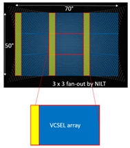
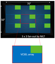
Using flat optics, the projected patterns might be tuned to match the application’s needs. For example, with 1D or 2D VCSEL addressable arrays, where only a particular area of the VCSEL is fired at the time, it is possible to map the scene using a temporal sequence of illumination patterns. The sensor area illuminated could thus be larger to ensure higher resolution, and the scene screening would be 3x faster for further processing at high vehicle speeds. The left section of the figure below shows a 1D addressable array where an entire column (or several) of emitters are switched on. On the right, show a specific 2D array of the VCSEL array is ON. Using flat optics fanout customization, the patterns from the VCSEL can be preserved while being duplicated to fill the region of illumination.
About NILT
NIL Technology (NILT) is an advanced optics company focusing on commercializing flat-optics for near-infra-red consumer applications. NILT has extensive design, modeling, fast-prototyping, and mass production capabilities for MOE(meta optical elements) and DOE elements and components on 6inch wafers. Most new consumer applications call for 940nm. However, NILT DOEs can be adjusted for 850nm-905-940nm and longer SWIR wavelengths. NILT is working with highly reliable processes and material passing 1000h reliability tests (TC, HTHH).