
Radiometry 101: Calibrating With Diffuse Reflecting Targets
By Matt Birkebak, Joshua Stearns, Chris Durell And Dan Scharpf
Without proper calibration, a remote sensing platform will not collect accurate radiometric data, imperiling mission-critical tasks where decisions are made based on that data.
Remote sensing observation of real targets using broadband, RGB, multispectral, or hyperspectral imaging instruments on small platform drones and UAVs requires proper calibrations to achieve quantifiable results. Many systems still use factory calibrations to measure radiance and do not baseline fundamental instrument performance for the actual sunlight illumination, geographic location, and atmospheric conditions in which they are used. Without proper calibration, the remote sensing platform will not collect accurate radiometric data.
Radiance reflected from objects in a scene can vary with solar, atmospheric, topographical, and obstructive (e.g., shade) conditions. Additionally, instruments used in the field often are subjected to harsh conditions, making their calibrations viable only over short time spans or a limited number of campaigns, while illumination conditions remain stable. To alleviate many of these problems, calibrated reflectance targets may be used as a radiometric baseline for instrument performance.
To minimize geometrical effects, calibrated targets with diffuse (near Lambertian) properties that have reflectance levels similar to the subject in question, and that are spectrally flat over a wide wavelength range, are ideal for this purpose. While performance tradeoffs exist for these targets, target features can be optimized based on the specific application — including the aforementioned atmospheric conditions, or to meet the desired characterization parameters of a camera or sensor test. In addition to hemispherical reflectance values, the target’s bidirectional reflectance distribution function (BRDF) also can be used to accurately characterize the target’s directional reflectance properties for improved sensor calibration.
Radiance/Irradiance Definitions
When incident light hits a reflective surface, the reflected light (radiance) received by an imaging device is the amount of power (flux) per solid angle, per projected area. The incident light on the surface is defined as the irradiance and includes all light, from all directions, that impinges the surface. The total flux emitted from the surface after diffusely reflecting is calculated from the integrated intensity.
A simple distinction between irradiance and radiance is that irradiance can be measured with a bare sensor (captures light from all directions), and radiance uses an imager (lens with a limited field of view) to capture light within a given solid angle. Radiance is important to understand as a baseline for this discussion, as it is used to predict the amount of flux that can be collected by an optical system that might view the illuminated surface.
Radiance And Reflectance
While remote sensing platforms calculate flux or other radiometric values from targets by directly measuring the radiance, the measured values are influenced by external illumination conditions that are subject to change. Factors such as system viewing angle, time of year, and atmospheric conditions directly affect the flux calculated from the radiance of the surface. Therefore, it is desirable to consider a more meaningful image parameter that is not subject to temporal fluctuation.
Calculating the reflectance (a ratio of incident radiance versus reflected radiance — see Fig. 1, value “C”) provides much more information about the targets within a scene by removing the dependence on illumination conditions, especially if the same scene will be compared to previous images under different illumination conditions. Reflectance is an intrinsic material property that can be calculated by remote sensing platforms using the ratio of measured radiance from the target over the total downwelling radiance incident on the target.
Additionally, the reflectance of most materials is not uniform over viewing angle. Remote imaging systems do not capture all light reflected from a target, only the light reflected in the direction of the camera. Thus, the reflectance predicted by the system is a function of illumination, material scattering properties, and viewing angle, and will change with camera and lightsource orientations relative to the viewed surface.
![]()
Figure 1. Transmission is the fraction of light passing through the target; reflectance is the fraction of light backscattered from the target. Any other losses are due to absorption.
The material’s directional scattering effects, or BRDF, cannot be ignored and must be used to correct the image for its particular viewing angle. Measuring or obtaining BRDF values can be difficult, and in most field measurements, its BRDF values are not well-defined for all materials. To work around this, it is useful to use the reflectance factor — a ratio of the measured reflectance to the reflectance of a standard Lambertian material placed within the scene (Fig. 2). The reflectance factor can be used to remove the angular dependence of reflectance in a given scene, and allows targets in the image to be normalized for the viewing angle. Using a Lambertian target in a field measurement provides a reliable way to compare targets in remote sensing applications.
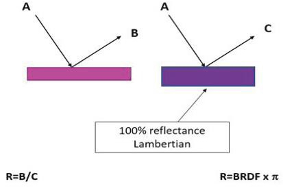
Figure 2. Reflectance factor (R)
Routine recalibrations with a calibration target are necessary to maintain accurate measurements due to changing illumination conditions and viewing angle. Changes in cloud cover, humidity, and temperature can significantly alter the calibration and should be avoided, if possible. By placing a calibrated Lambertian target in the image, corrections for viewing angle can be made, as well as compensation for any atmospheric effects.
What Makes A Good Target?
In very simple applications, plywood painted with a matte finish can suffice as a target. Problems with this approach can include target flatness, nonuniform surface finish or paint application, and, most critically, the unknown reflectance values and non- Lambertian BRDF (Fig. 3). In addition, the paint’s finish can degrade and become discolored over time, due to weathering and UV exposure over long periods. Extended exposure to UV will change the panel’s spectral reflectance (and perceived color), severely affecting the measurement performed by the optical instrument during calibration with the target.
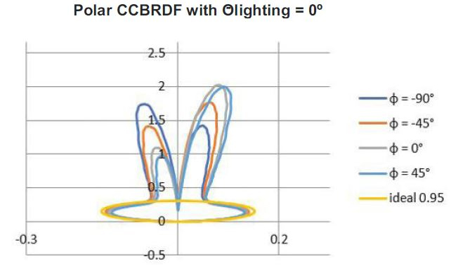
Figure 3. BRDF of a typical white paint. It is very specular compared to an ideal Lambertian reflector shown in yellow.
If the panel has been calibrated, it will need much more frequent calibration to account for these changes in performance. Additionally, most common paints are not particularly stable for these scientific applications and have poor BRDF or reflectance properties in the visible (VIS) range, where there can be sharp drops in reflectance.
Using a calibration target that has poor performance characteristics (e.g., non-Lambertian, nonuniform reflectance spectrum) may not provide the camera with a valid calibration. For example, a poorly characterized target used to calibrate a good multiband camera using NDVI band ratios may misidentify healthy vegetation as sick or stressed, based on an erroneous baseline from the target.
To properly define the performance requirements for a calibration target, the measurement application’s goals must be defined. For many applications, such as LiDAR and image and sensor calibration, a near-perfect diffuse reflectance material that spans the UV – VIS – NIR spectrum makes the measurement considerably simpler. Measuring this ideal material is known as ground truthing, since it provides an absolute reference for the subsequent measurements.
The ideal material/coating for ground truthing would be durable, high-in-reflectance, spectrally flat over a wide wavelength range, and able to withstand long exposure to harsh environmental conditions, such as UV, rain, and wind. In addition, the ideal target should be functional across laboratory, production, and field use, so that cross-referencing is possible. For field use, the distance between the imaging device and the target, the camera resolution, and the field of view will dictate the size of the target, necessitating a target that is lightweight and portable.
To create a near-Lambertian reflectance, some polymers and thermoplastic materials utilize volume scattering, where the light enters the porous material structure, is scattered by multiple reflections, and then emits back out through the surface. While this provides a near-Lambertian profile, this type of porous structure can be susceptible to absorbing dust, dirt, greases, and oils and needs to be kept clear of contaminants, thus making it unfit for outdoor or dirty environments. Due to these realities of field measurement, consideration of the target environment should drive what reflectance material is chosen.
Sintered PTFE has been shown to be effective for Lambertian scattering (Fig. 4) over a range of lighting conditions, wavelength ranges, and reflectance levels, making it an ideal material for reflectance targets in remote sensing applications. In some applications, it is desired to have the calibration target match the reflectance of the material in question, and having targets with reflectance values ranging from 5 percent (gray targets) to 95 percent is ideal. As long as the reflectance is relatively flat, spectrally (compared to the target signature), the reference reflectance material will allow for proper calibration.
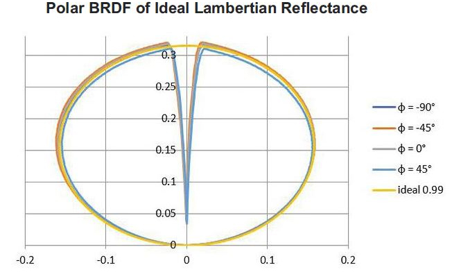
Figure 4. Example of an ideal Lambertian material. The BRDF plot appears circular for this ideal case.
When durability and weight constraints are issues, BaSo4 - based targets are ideally suited, since they are a spray-on coating that can be applied to lightweight panels and made into very large sizes (>3m) for a variety of applications (e.g. LiDAR for ADAS). Reflectance uniformity across the surface of the panels can also be maintained within ±1 percent, making it ideal as a target used at long distances. The reflectance levels of these materials can also be tuned from 3 percent to 95 percent for the appropriate application and used in the NIR laser wavelengths of 908nm and 940nm and up to 1550nm. Unlike paper targets, some spray-on coatings can also be cleaned and reused and have been shown to be highly UV-resistant, making them ideal for applications exposed to changing weather conditions, varied lighting conditions, and multiple environments, due to the material’s uniform spectral response, thermal characteristics, and durability.
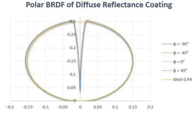
Figure 5. BRDF of BaSo4 coating with 94% reflectance
What Reflectance Is Needed?
Ideally, a calibration material will have a reflectance level similar to that of the target object or the average scene reflectance in order to maintain a high signal-to-noise ratio (SNR) on the measurement instrument. It is useful to have a range of calibration standards with well-documented reflectivity, such that the appropriate one can be chosen for the imaging application. Additionally, having multiple target reflectance values also may allow the user to determine other aspects of the camera, such as linear response.
Since most remote sensing applications deal with a wide dynamic range of reflectance and light sources, there is no one-size-fits-all target that can be selected as the calibration source. It is possible that, if the calibration target has too high a reflectance, it may saturate the image, producing an incorrect calibration. Generally, a calibration standard with reflectance within 20 to 5 percent of the target object is desired, and, ideally, the responsivity of the camera to this target will provide a high SNR.
Sizing The Target, Field Of View, And Number Of Pixels
The target must be appropriately sized for the application and should be large enough to be seen clearly by the imaging sensor. Typically, it is recommended that the target fill a minimum of 7 to 12 pixels in the image in order for the center pixel to be a calibrated pixel. A single pixel or lower number of pixels on the target is not sufficient for calibrations, due to real camera optical system limitations, such as pixel-edge effects, point spread function (PSF), and camera focus. The more pixels on the target, the more calibrated pixels can be obtained.
The exact size of the target can then be selected based on the instantaneous field of view (iFOV) of the camera pixels and distance to the target. Fig. 6 provides an example of reflectance standards placed in a large field within the image. The targets have different reflectance values to help the camera establish linearity over a range of reflectance values. The targets also are large enough to fill an adequate number of the camera’s pixels.
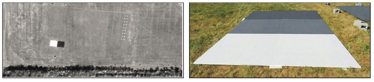
Figure 6. Grass field with varied reflectance calibration targets
Summary
Using a calibrated reflectance target as a radiometric baseline for instrument performance can alleviate many of the problems associated with variability in radiance due to atmospheric conditions during flight times. However, these targets only work if they’re a diffuse (Lambertian) coating that has a known reflectance and BRDF and are spectrally flat over a wide wavelength. With UAV applications (e.g. agriculture, autonomous vehicles, etc.) on the rise and the importance of health and safety in such applications, it becomes more important for these cameras and sensors to provide accurate feedback to the users and autonomous systems to make decisions based on validated data.
Matt Birkebak is a product engineer at Labsphere, working with customers to solve their calibration needs. Prior to that, he received a B.S.M.E. at the University of New Hampshire in 2015, followed by an M.S. in ocean engineering, where he studied underwater optical remote sensing techniques. He is interested in the analysis of uncertainty in LiDAR remote sensing.
Joshua Stearns is a product marketing manager for Labsphere’s remote sensing product line. Joshua graduated from SNHU (Southern New Hampshire University), where he received a B.S. in marketing in 2007 and his MBA in 2012. He joined Labsphere in September 2017 and previously held sales and marketing positions for advanced laser technology companies in the photonics industry for nearly a decade.