
Production Testing of High-Intensity, Visible LEDs

Table of Contents
Test Descriptions
Test System Description
Typical Sources of Error in LED Testing
Summary
Visible light emitting diodes (LEDs) offer long life and high reliability, and thus are finding their way into more and more applications. LEDs are now used in automobiles (including extremely bright brake light assemblies), street lights, consumer electronics, and outdoor signs, just to name a few. Furthermore, LEDs are now available in virtually all colors, including blue. This opens the door to LED use in the widest range of applications, including those where reliability is a critical concern. Therefore, thorough yet cost-effective testing methods are increasingly important. In addition, new LED technologies, such as high-intensity LEDs and organic LEDs, have placed added demands on test equipment in the form of improved measurement performance and throughput.
Test Descriptions
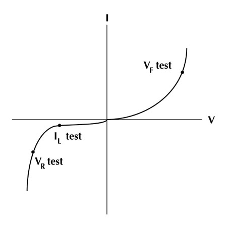
LEDs produce light as the result of the transition of charged particles across the semiconductor energy gap. The value of this energy gap determines the wavelength of the emitted light. LED technologies have progressed to the point where wavelength and power attributes can both be varied during manufacture. Typically, high-performance LEDs are subjected to five tests. These include three tests involving DC electrical parameters (forward voltage, reverse breakdown and leakage current) and two tests in the optical domain (luminous intensity and wavelength verification). To maximize throughput in the production environment, testing is generally limited to DC parameters only. While useful in many cases, optical tests can be slow, and are typically reserved for the engineering or quality control lab. Figure 1 illustrates the test points for each of the three DC tests described in this article.
DC TESTS
The forward voltage (VF) test verifies the forward operating voltage versus current flowing through the visible LED. In practice, a specified forward bias current (for example, 10mA) is applied for a specific time (e.g. 1ms), and the voltage drop across the LED is measured (typically hundreds of millivolts).
The reverse voltage (VR) test verifies the reverse breakdown voltage of the LED, and is similar to the reverse breakdown test for a standard diode. Beyond a certain current level, large increases in reverse bias current produce insignificant changes in reverse voltage. During the VR test, a low-level reverse bias current is forced through the LED, and the resulting voltage drop is measured (typically volts to tens of volts).
The VR characteristics of the LED give an indication of the LED's polarity in one of two ways. A positive current can be sourced through the LED, and a voltage of less than 1V generally indicates forward polarity of the diode, while a high voltage indicates breakdown and reverse polarity. The VR test instrument can then indicate to the device handler whether the device should be flipped.
The IL test verifies the LED's leakage current (typically nanoamps to microamps), which is the low-level current that flows through the LED when a reverse voltage less than breakdown (VR) is applied.
OPTICAL TESTS
The radiant intensity measurement accounts for the total output of the LED (typically 1 µWatt/steradian to tens of mW/sr, while luminous intensity measures output over the visible range. Luminous efficiency can also be calculated by dividing the total luminous output in lumens/watt by the input power. Light intensity is often measured using a photodetector (PD). The amount of reverse current present through the PD is proportional to the amount of light shining on the PD. The PD reverse current can be measured, and the LED's light intensity extrapolated from that measurement. This method of performing LED light intensity measurement enables the entire test system for DC and optical test to be constructed using only high-speed DC instruments.
Wavelength data is obtained using a spectrometer, a type of optical instrument that measures the dominant and peak output wavelengths of the LED. The output spectrum of an LED, known as the far-field pattern (FFP), resembles a bell curve centered on the peak wavelength. Full width at half maximum (FWHM) is calculated as the spectral bandwidth at half intensity, and is used to specify the operating wavelength range of the LED. The color information for the LED output can be obtained using an ISO/CIE standard colorimetric system, which measures the LED's output based on its relative content of the three primary colors (red, blue and green).
Test System Description
The instruments used to perform the three DC tests on the LED should have bi-polar source/measure (voltage and current) capabilities to avoid having an operator flip or move the LED from the initial test position (see Figure 2). The instrumentation should also be capable of capturing light intensity data by performing a multi-point current sweep on the LED over its operating range, and then measuring light output using a PD with a suitable readout device. Because the PD output is a low-level current, a sensitive measurement instrument such as a picoammeter or electrometer is usually required. For high throughput applications, the light intensity is generally measured over a few test points.
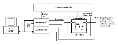
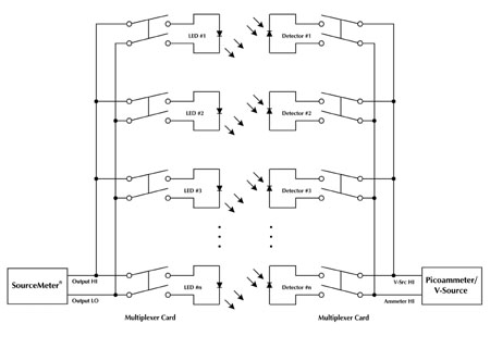
For LED arrays, multi-die packages, or burn-in applications, it is more efficient to test many LEDs at once. Switching enables fewer readout instruments to be used, and provides a convenient method of connecting many devices to a single instrument. In multiple device test systems, an individual LED is selected for testing by closing relays to connect an LED and corresponding PD to the instrumentation. The measuring instrument performs the desired DC tests, and an electrometer measures the output of the PD while the LED is on. Once the process is completed, the switching matrix selects the next LED for testing.
Typical Sources of Error in LED Testing
Junction Self-Heating
The semiconductor junction of an LED tends to heat from current flow, and heating increases with test times, such as during the forward voltage and leakage current tests. Therefore, it is important to shorten the test time as much as possible by adjusting the instrument's measurement and soak times.
Lead Resistance
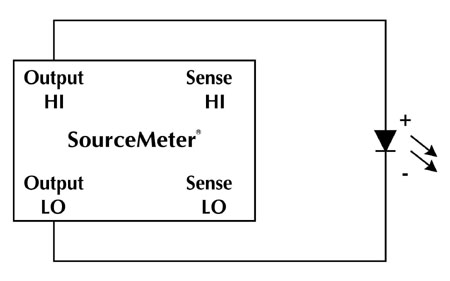
A common source of voltage measurement error is the series resistance of the test leads running from the source and measurement instruments to the LED. Ordinary two-wire measurement techniques tend to see this resistance as part of the device under test (Figure 3a). This effect is particularly detrimental when long connecting cables and high current are used, because the voltage drop across the lead resistance becomes a significant part of the total voltage measurement.
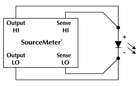
The four-wire remote sensing method (Figure 3b) can be used to overcome the limitations of the two-wire technique. With the four-wire method, a current is forced through the LED using current sourcing leads (in this case, the Output HI/LO leads of a combined Source-Measure instrument), and the voltage across the LED is measured using separate Sense HI/LO leads. Virtually no current flows in the Sense leads, so the voltage measurement consists of just the voltage drop across the device.
Leakage Current
Leakage currents in cables and fixtures can be a source of error when extremely low currents are measured (typically, less than 10A). To minimize these problems, insulation in test fixtures and cables must be made of materials having impedances much higher than the impedances being tested. Guarding reduces measurement errors by eliminating leakage paths between insulated conductors on a circuit board, device under test, or in a cable or a connector. Typically, a meter having a guard output is required to perform guarded measurements (see Figure 4).
Electrostatic Interference
Noise can come from many sources in the production environment. To minimize the effects of this electrostatic interference, ensure that all system cabling is properly shielded. Whether the system cabling is single- or multiconductor, use one shield around the wire bundle. Where necessary, build a shielded enclosure around test fixtures. All shields should be connected to a single ground point in the system to eliminate the possibility of ground loops.
Light Interference
Testing LEDs involves detecting the amount and intensity of light produced by the LED, so the test fixture should be shielded from light. Typically, the inside of a test fixture is painted black to reduce reflection.
Summary
The testing of visible LEDs is becoming more competitive as these components find their way into new applications; economies of scale cannot be realized unless testing is equally cost effective. Increasingly, automated instruments with feature sets designed for specific test applications are the key to competitive manufacturing. The foregoing discussion describes several standard tests associated with visible LEDs. The text shows that, in many cases, a few instruments, such as a source-measurement unit, an electrometer, and a switching matrix, can perform the necessary tests without complex test system design or needless duplication of instruments.
About the author…
Doug Rathburn is a senior applications engineer at Keithley Instruments where he is responsible for customer support, training, writing application software, and technical documentation. He received B.S.E.E., B.A. – Economics, and M.E. – Systems Engineering from Case Western Reserve University in Cleveland, Ohio.