
Overcoming The Unique Challenges Of Coating Aspheres
By Cory Boone, Technical Marketing Manager, Edmund Optics

The complex, non-spherical surfaces of aspheric lenses result in a number of benefits for optical system designers. Compared to conventional spherical lenses, aspheres result in better resolution, higher light throughput, and even a reduction in the number of optical elements required to achieve a certain level of performance. These benefits are achieved because of aspheres' correction of spherical and higher-order aberrations.
Aspheric surfaces, however, often feature sharper surface angles than conventional lenses, and this steepness introduces some unique challenges during the coating process. Coating effects resulting from steep surface angles can cause unwanted reflections, reducing light throughput. Thankfully, diligent attention to coating parameters and coating layer materials can reduce the impact of these effects. A knowledge of the effects of surface steepness on coating performance aids optical system designers in choosing the optimal coating designs for their given application.
Why Are Aspheres Often Steeper Than Other Lenses?
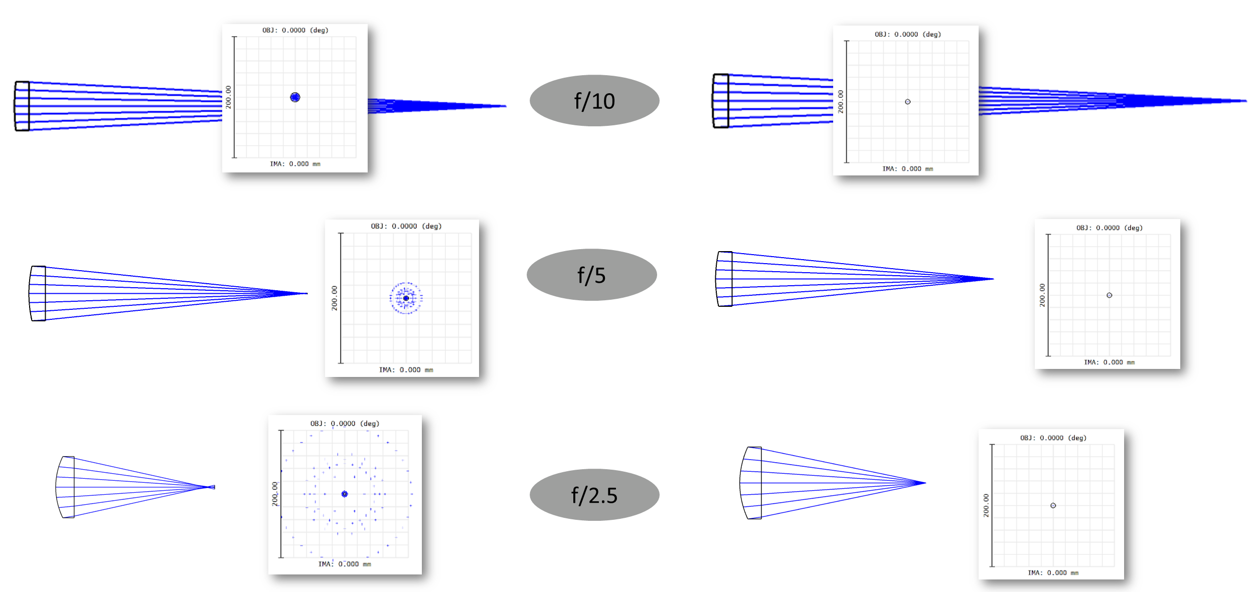
Aspheric lenses often have steeper surfaces than spherical lenses simply because they can without sacrificing performance. A lens' f/#, defined as its focal length divided by its effective aperture diameter, has a direct effect on the size of the lens' diffraction-limited focused spot size. Smaller f/#s, which also mean a larger numerical aperture, allow for a smaller focused spot size. This is almost always beneficial for the application's performance. However, in reality, reducing a lens' f/# by either moving to a shorter focal length or larger effective aperture diameter leads to the introduction of more spherical aberrations. This increases focused spot size and worsens lens performance. Because of this, traditional lenses keep f/# comparatively large so to balance the effects of spherical aberration and diffraction-limited performance.
Figure 1 shows the spot size for both conventional spherical lenses and comparable aspheres at different f/#s. The lenses on the left are spherical and the lenses on the right are aspheric. The spot diagrams reveal that the actual focused spot size of spherical lenses significantly increases at smaller f/#'s, while the spot diagrams of aspheres remain small. This allows aspheres to reap the benefits of smaller f/#'s without sacrificing resolution. However, steep lens surfaces are needed to reach these low f/#'s. It should be noted that Figure 1 displays some spot sizes smaller than the diffraction limit because this simulation was conducted in the optical design software Zemax OpticStudio and based on geometrical ray tracing, not physical optics propagation. In reality, focused spot size is limited by the diffraction limit.
How Do Sharp Surface Angles Affect Coating?
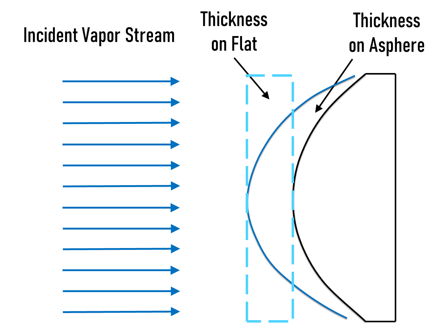
Two primary effects are introduced by steep aspheric surfaces that can impact coating performance: the deposition effect and the angle-of-incidence (AOI) effect. The deposition effect is dependent on the lens' geometry and occurs during the coating process. It describes how the thickness of a coating deposited on a curved lens is thicker in the center than it will be on the edges of the lens. If the optical surface was flat, atoms deposited during the coating process would arrive uniformly across the surface and form a layer of uniform thickness (Figure 2). But because curved surfaces have larger surface areas than flat surfaces, the coating must end up thinner toward the edges of the lens. This is due to the conservation of mass. While the optic's edges will have thinner coating layers, the center of the lens will have about the same coating thickness of a flat optic coated under similar conditions. Steeper angles of lens curvature, like those associated with low f/#'s, amplifies the impact of the deposition effect. Thinner coatings shift the spectral performance of the lens to longer wavelengths. Because of this, the center of the lens will perform differently than the lens edges.
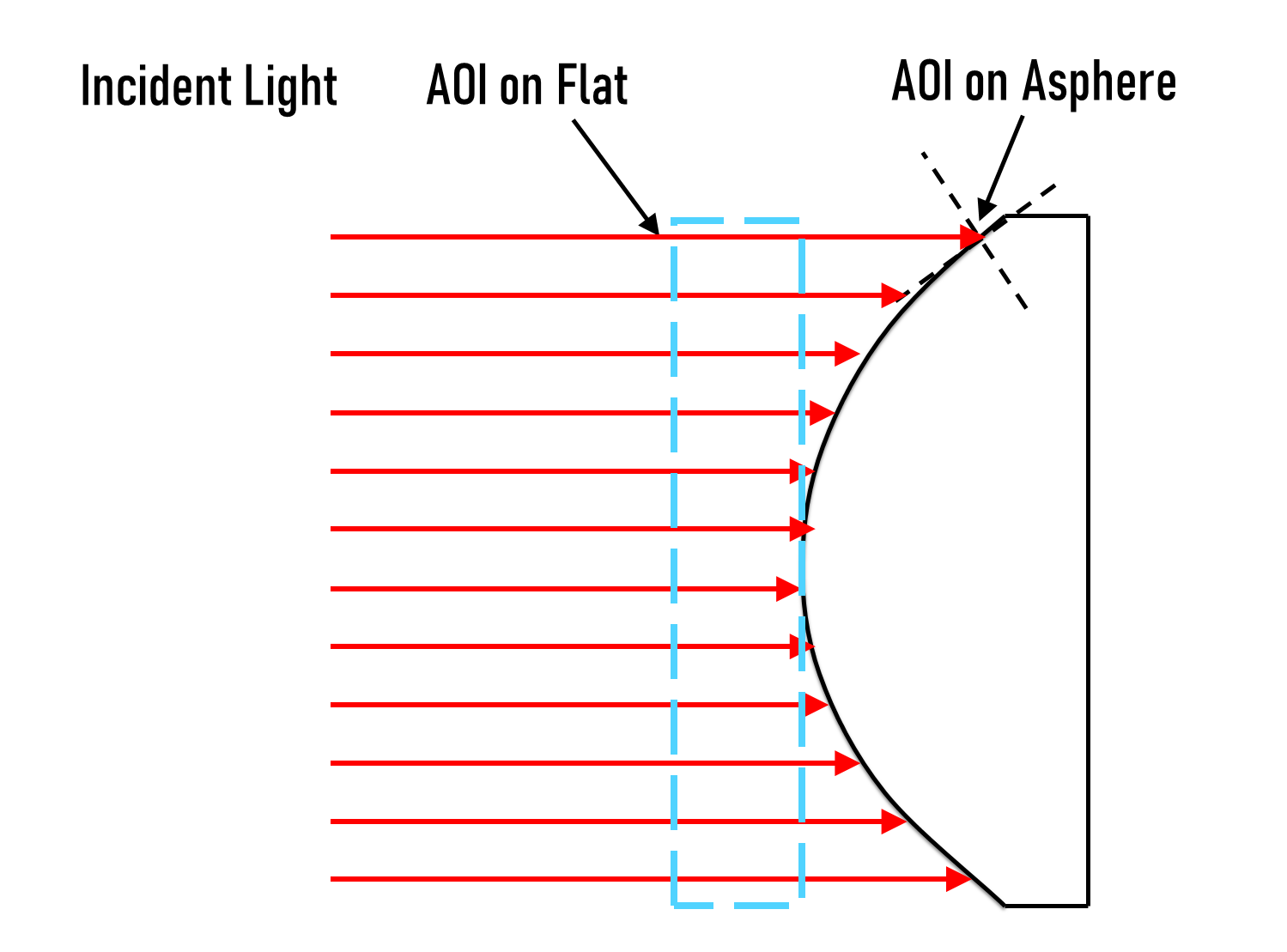
On the other hand, the AOI effect is expressed in the end application, not during the coating process (Figure 3). Incident collimated light rays encounter larger incident angles toward the lens' edges compared to its center. These larger edge AOIs also cause a spectral performance shift to longer wavelengths. Like the deposition effect, the impact of this effect is more significant for steeper surface angles compared to more gradually-sloping lenses.
Real-World Impact Of The Deposition And AOI Effects
While both the deposition and AOI effects change performance based on lens diameter, since rays at the edges are simultaneously contacting thinner coating layers and coming in at higher angles, we will ignore the convolution of these two effects and evaluate them separately for simplicity's sake.
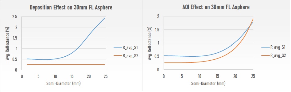
In addition to shifting performance to longer wavelengths, both the deposition and AOI effects can also introduce unwanted reflections, reducing light throughput. To illustrate this, both effects will be investigated for a plano-convex asphere with a 30mm focal length, 50mm diameter, simple magnesium fluoride (MgF2) coating on the curved surface, and an N-SF6 substrate. The AOI of rays incident on and leaving the asphere were modeled using Zemax OpticStudio.
Figure 4 reveals unwanted reflectance increases as a function of lens semi-diameter. In the diagrams below, "S1" refers to the aspheric surface and "S2" is the flat back surface. Average reflectance is displayed across the wavelength range of 425 – 625nm. Semi-diameters from about 0 – 12.5mm, corresponding to angles of incidence around 0 – 30°, show minimal reflectance increases from either the deposition or AOI effect. But at semi-diameters above 12.5mm, a clear increase in reflectance can be observed with the exception of no deposition effect impact on the planar side of the lens ("R_avg_S2" on the left of Figure 4). Both effects have a noticeable consequence to lens performance. It should also be noted that, for semi-diameters above 12.5mm, the deposition effect has a sharper increase in reflectance compared to the AOI effect.
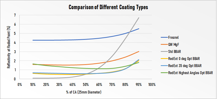
Different types of coatings respond differently to these two effects. Figure 5 examines the differences in performance degradation for various types of coatings from Edmund Optics® as a function of how much of the clear aperture (CA) of a 25mm lens is used. Interestingly, some coatings that have lower reflectivity at smaller AOIs are more sensitive to surface angle and therefore more sharply increase reflectivity at larger semi-diameters. For example, the Standard Broadband Anti-Reflection coating, titled "Std BBAR", exhibits great performance when only a small percentage of the CA is filled, but reflectivity increases more sharply than other coating types by the lens edges. Because of behaviors like this, coatings that may at first not seem like optimal choices, like MgF2, may actually provide higher transmission as a whole when the performance towards the lens' edges is considered.
Unfortunately, no one-size-fits-all approach lets optical system designers select the best lenses or coatings for all situations. Optical component manufacturers can adjust many different parameters in lens design, fabrication, and coating to balance different specifications for the best overall performance. Discuss these principles with your optical manufacturer when specifying aspheric lenses to ensure that the proper coating and lens geometry are used to achieve both the resolution and spectral performance needed for your end application.