
IR Thermography – How It Works
IR Thermography Cameras
Although infrared radiation (IR) is not detectable by the human eye, an IR camera can convert it to a visual image that depicts thermal variations across an object or scene. IR covers a portion of the electromagnetic spectrum from approximately 900 to 14,000 nanometers (0.9–14 μm). IR is emitted by all objects at temperatures above absolute zero, and the amount of radiation increases with temperature.
Thermography is a type of imaging that is accomplished with an IR camera calibrated to display temperature values across an object or scene. Therefore, thermography allows one to make non-contact measurements of an object’s temperature.
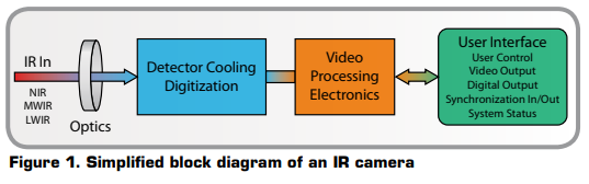
IR camera construction is similar to a digital video camera. The main components are a lens that focuses IR onto a detector, plus electronics and software for processing and displaying the signals and images. Instead of a charge coupled device that video and digital still cameras use, the IR camera detector is a focal plane array (FPA) of micrometer size pixels made of various materials sensitive to IR wavelengths. FPA resolution can range from about 160 × 120 pixels up to 1024 × 1024 pixels. Certain IR cameras have built-in software that allows the user to focus on specific areas of the FPA and calculate the temperature. Other systems utilized a computer or data system with specialized software that provides temperature analysis. Both methods can supply temperature analysis with better than ±1°C precision.
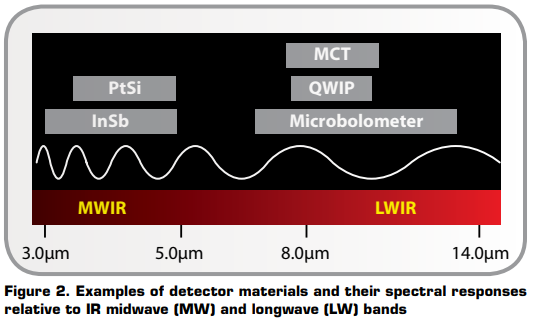
FPA detector technologies are broken down into two categories: thermal detectors and quantum detectors. A common type of thermal detector is an uncooled microbolometer made of a metal or semiconductor material. These typically have lower cost and a broader IR spectral response than quantum detectors. Still, microbolometers react to incident radiant energy and are much slower and less sensitive than quantum detectors. Quantum detectors are made from materials such as InSb, InGaAs, PtSi, Hg-CdTe (MCT), and layered GaAs/AlGaAs for QWIP (Quantum Well Infrared Photon) detectors. The operation of a quantum detector is based on the change of state of electrons in a crystal structure reacting to incident photons. These detectors are generally faster and more sensitive than thermal detectors. However, they require cooling, sometimes down to cryogenic temperatures using liquid nitrogen or a small Stirling cycle refrigerator unit.
IR Spectrum Considerations
Typically, IR cameras are designed and calibrated for a specific range of the IR spectrum. This means that the optics and detector materials must be selected for the desired range. Figure 2 illustrates the spectral response regions for various detector materials.
Because IR has the same properties as visible light regarding reflection, refraction, and transmission, the optics for thermal cameras are designed in a fashion similar to those of a visual wavelength camera. However, the types of glass used in optics for visible light cameras cannot be used for optics in an infrared camera, as they do not transmit IR wavelengths well enough. Conversely, materials that are transparent to IR are often opaque to visible light.
IR camera lenses typically use silicon (Si) and germanium (Ge) materials. Normally Si is used for MWIR (medium wavelength IR) camera systems, whereas Ge is used in LW (long wavelength) cameras. Si and Ge have good mechanical properties, i.e., they do not break easily, they are non-hygroscopic, and they can be formed into lenses with modern turning methods. As in visible light cameras, IR camera lenses have antireflective coatings. With proper design, IR camera lenses can transmit close to 100 percent of incident radiation.
Thermal Radiation Principles
The intensity of the emitted energy from an object varies with temperature and radiation wavelength. If the object is colder than about 500°C, emitted radiation lies completely within IR wavelengths. In addition to emitting radiation, an object reacts to incident radiation from its surroundings by absorbing and reflecting a portion of it, or allowing some of it to pass through (as through a lens). From this physical principle, the Total Radiation Law is derived, which can be stated with the following formula:
W = αW + ρW + tW,
which can be simplified to:
1 = α + ρ + t.
The coefficients α, ρ, and τ describe the object’s incident energy absorbtion (α), reflection (ρ), and transmission (τ). Each coefficient can have a value from zero to one, depending on how well an object absorbs, reflects, or transmits incident radiation. For example, if ρ = 0, τ = 0, and α = 1, then there is no reflected or transmitted radiation, and 100 percent of incident radiation is absorbed. This is called a perfect blackbody.
In the real world, there are no objects that are perfect absorbers, reflectors, or transmitters, although some may come very close to one of these properties. Nonetheless, the concept of a perfect blackbody is very important in the science of thermography because it is the foundation for relating IR radiation to an object’s temperature.
Fundamentally, a perfect blackbody is a perfect absorber and emitter of radiant energy. This concept is stated mathematical as Kirchhoff’s Law. The radiative properties of a body are denoted by the symbol ε, the emittance or emissivity of the body. Kirchhoff’s law states that α = ε, and since both values vary with the radiation wavelength, the formula can take the form α(λ) = ε(λ), where λ denotes the wavelength.
The total radiation law can thus take the mathematical form 1 = ε + ρ + τ, which for an opaque body (τ = 0) can be simplified to 1 = ε + ρ or ρ = 1 – ε (i.e., reflection = 1 – emissivity). Since a perfect blackbody is a perfect absorber, ρ = 0 and ε = 1.
The radiative properties of a perfect blackbody can also be described mathematically by Planck’s Law. Since this has a complex mathematical formula and is a function of temperature and radiation wavelength, a blackbody’s radiative properties are usually shown as a series of curves (Figure 3).
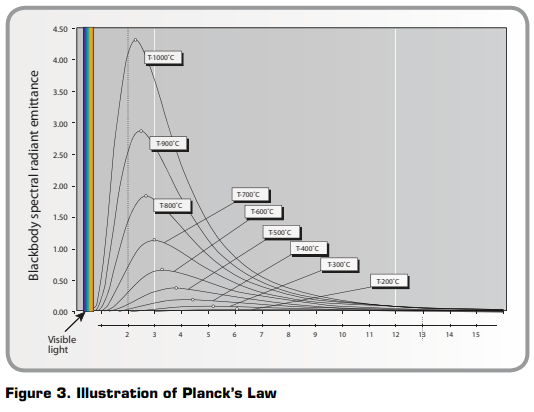
These curves show the radiation per wavelength unit and area unit, called the spectral radiant emittance of the blackbody. The higher the temperature, the more intense the emitted radiation. However, each emittance curve has a distinct maximum value at a certain wavelength. This maximum can be calculated from Wien’s displacement law,
λmax = 2898/T,
where T is the absolute temperature of the blackbody, measured in Kelvin (K), and λmax is the wavelength at the maximum intensity. Using blackbody emittance curves, one can find that an object at 30°C has a maximum near 10μm, whereas an object at 1000°C has a radiant intensity with a maximum of near 2.3μm. The latter has a maximum spectral radiant emittance about 1,400 times higher than a blackbody at 30°C, with a considerable portion of the radiation in the visible spectrum.
From Planck’s law, the total radiated energy from a blackbody can be calculated. This is expressed by a formula known as the Stefan-Boltzmann law,
W = σT4 (W/m2),
where σ is the Stefan-Boltzmann’s constant (5.67 × 10⁻⁸ W/m2K4). As an example, a human being with a normal temperature (about 300 K) will radiate about 500W/m2 of effective body surface. As a rule of thumb, the effective body surface is 1m2, and radiates about 0.5kW — a substantial heat loss.
The equations described in this section provide important relationships between emitted radiation and temperature of a perfect blackbody. Since most objects of interest to thermographers are not perfect blackbodies, there needs to be some way for an IR camera to graph the temperature of a “normal” object.
Emissivity
The radiative properties of objects are usually described in relation to a perfect blackbody (the perfect emitter). If the emitted energy from a blackbody is denoted as Wbb, and that of a normal object at the same temperature as Wobj, then the ratio between these two values describes the emissivity (ε) of the object,
ε = Wobj / Wbb.
Thus, emissivity is a number between 0 and 1. The better the radiative properties of the object, the higher its emissivity. An object that has the same emissivity ε for all wavelengths is called a greybody. Consequently, for a greybody, Stefan-Boltzmann’s law takes the form
W = εσT4 (W/m2),
which states that the total emissive power of a greybody is the same as that of a blackbody of the same temperature reduced in proportion to the value of ε for the object.
Still, most bodies are neither blackbodies nor greybodies. The emissivity varies with wavelength. As thermography operates only inside limited spectral ranges, in practice it is often possible to treat objects as greybodies. In any case, an object having emittance that varies strongly with wavelength is called a selective radiator. For example, glass is a very selective radiator, behaving almost like a blackbody for certain wavelengths, whereas it is rather the opposite for other wavelengths.
Atmospheric Influence
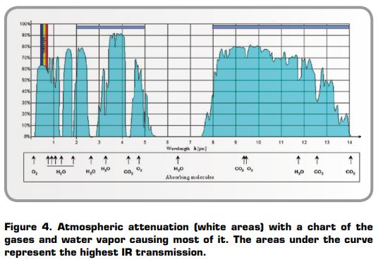
Between the object and the thermal camera is the atmosphere, which tends to attenuate radiation due to absorption by gases and scattering by particles. The amount of attenuation depends heavily on radiation wavelength. Although the atmosphere usually transmits visible light very well, fog, clouds, rain, and snow can prevent us from seeing distant objects. The same principle applies to infrared radiation.
For thermographic measurement we must use the so-called atmospheric windows. As can be seen from Figure 4, they can be found between 2 and 5μm, the mid-wave windows, and 7.5–13.5μm, the long-wave window. Atmospheric attenuation prevents an object’s total radiation from reaching the camera. If no correction for attenuation is applied, the measured apparent temperature will be lower and lower with increased distance. IR camera software corrects for atmospheric attenuation.
Typically, LW cameras in the 7.5–13.5μm range work well anywhere that atmospheric attenuation is involved because the atmosphere tends to act as a high-pass filter above 7.5μm (Figure 4). The MW band of 3–5μm tends to be employed with highly sensitive detectors for high-end R&D and military applications. When acquiring a signal through the atmosphere with MW cameras, selected transmission bands must be used where less attenuation takes place.
Temperature Measurements
The radiation that impinges on the IR camera lens comes from three different sources. The camera receives radiation from the target object, plus radiation from its surroundings that has been reflected onto the object’s surface. Both of these radiation components become attenuated when they pass through the atmosphere. Since the atmosphere absorbs part of the radiation, it will also radiate some itself (Kirchhoff’s law).
Given this situation, we can derive a formula for the calculation of the object’s temperature from a calibrated camera’s output.
- Emission from the object = ε τ Wobj, where ε is the emissivity of the object and τ is the transmittance of the atmosphere.
- Reflected emission from ambient sources = (1 – ε) τ Wamb, where (1 – ε) is the reflectance of the object. (It is assumed that the temperature Tamb is the same for all emitting surfaces within the half sphere seen from a point on the object’s surface.)
- Emission from the atmosphere = (1 – τ) W the emissivity of the atmosphere.
The total radiation power received by the camera can now be written:
Wtot = ε · t · Wobj + (1 – ε) · t · Wamb + (1 – t) · Watm,
where ε is the object emissivity, τ is the transmission through the atmosphere, Tamb is the (effective) temperature of the object’s surroundings, or the reflected ambient (background) temperature, and Tatm is the temperature of the atmosphere.
To arrive at the correct target object temperature, IR camera software requires inputs for the emissivity of the object, atmospheric attenuation and temperature, and temperature of the ambient surroundings. Depending on circumstances, these factors may be measured, assumed, or found from look-up tables.
...
Click here to download the full PDF version.