
Introduction to Laser Damage Threshold (LDT)
By Cory Boone, Technical Marketing Manager, Edmund Optics
Laser damage threshold (LDT) is one of the most crucial specifications for designing high power laser systems for applications ranging from materials processing to medical devices. As defined in the ISO 21254 standard, LDT is the “highest quantity of laser radiation incident upon the optical component for which the extrapolated probability of damage is zero”.1 The purpose of LDT is to clarify what kinds of lasers are compatible with an optical component or assembly. It specifies the maximum laser fluence (typically in J/cm2 for pulsed lasers) or the maximum laser intensity (typically in W/cm2 for continuous wave [CW] lasers) that an optic can handle before damaging (Figure 1).
However, the statistical nature of laser damage testing results in LDT not guaranteeing that the chance of damage is zero below its value, but rather that the risk level is below a critical value below the LDT. The exact amount of risk of damage is dependent on several factors including beam diameter, number of test sites per sample, and number of samples tested to determine the specification.
The laser-induced damage of optics both degrades overall system performance and can potentially lead to catastrophic failure. This can lead to increased costs and even dangerous situations. Especially in high-power laser systems, LDT is important for all types of laser optics including transmissive, reflective, and absorptive components. A lack of industry-wide consensus on LDT testing and the interpretation of that data makes LDT a complicated parameter. An LDT fluence or intensity on its own does not convey the beam diameter used in testing, the number of shots per testing site, or the way the testing data was analyzed.
Understanding LDT
To evaluate whether a particular laser fluence or power may damage an optic, the following key parameters of the laser should be reviewed: power, beam diameter, and whether the laser is CW or pulsed. Pulse duration should also be considered for pulsed lasers.
Intensity: More Complicated Than It Seems
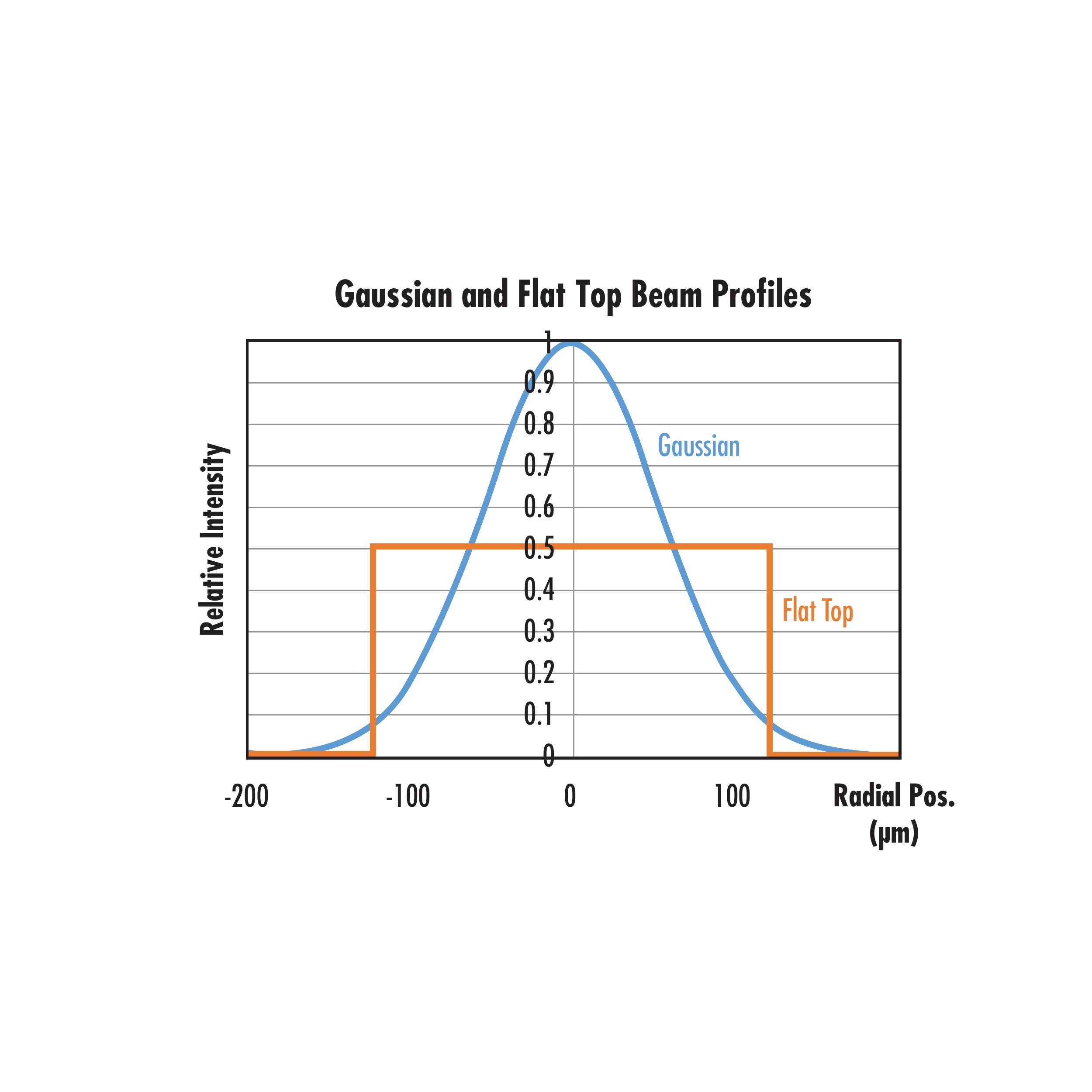
A laser beam's intensity is specified as optical power per unit area, usually measured in W/cm2. The laser's energy distribution across a cross-section of the beam is referred to as the intensity profile. Two of the most commonly found intensity profiles are Gaussian and flat top beams. Gaussian beams are characterized by an intensity profile with a maximum value in the center and decreasing intensity as the distance from the beam's center increases following a Gaussian function. Flat top, or top hat, beams feature an intensity profile of a constant value across a cross-section of the beam. The peak intensity of a Gaussian beam is double that of a flat top beam of the same optical power (Figure 2).
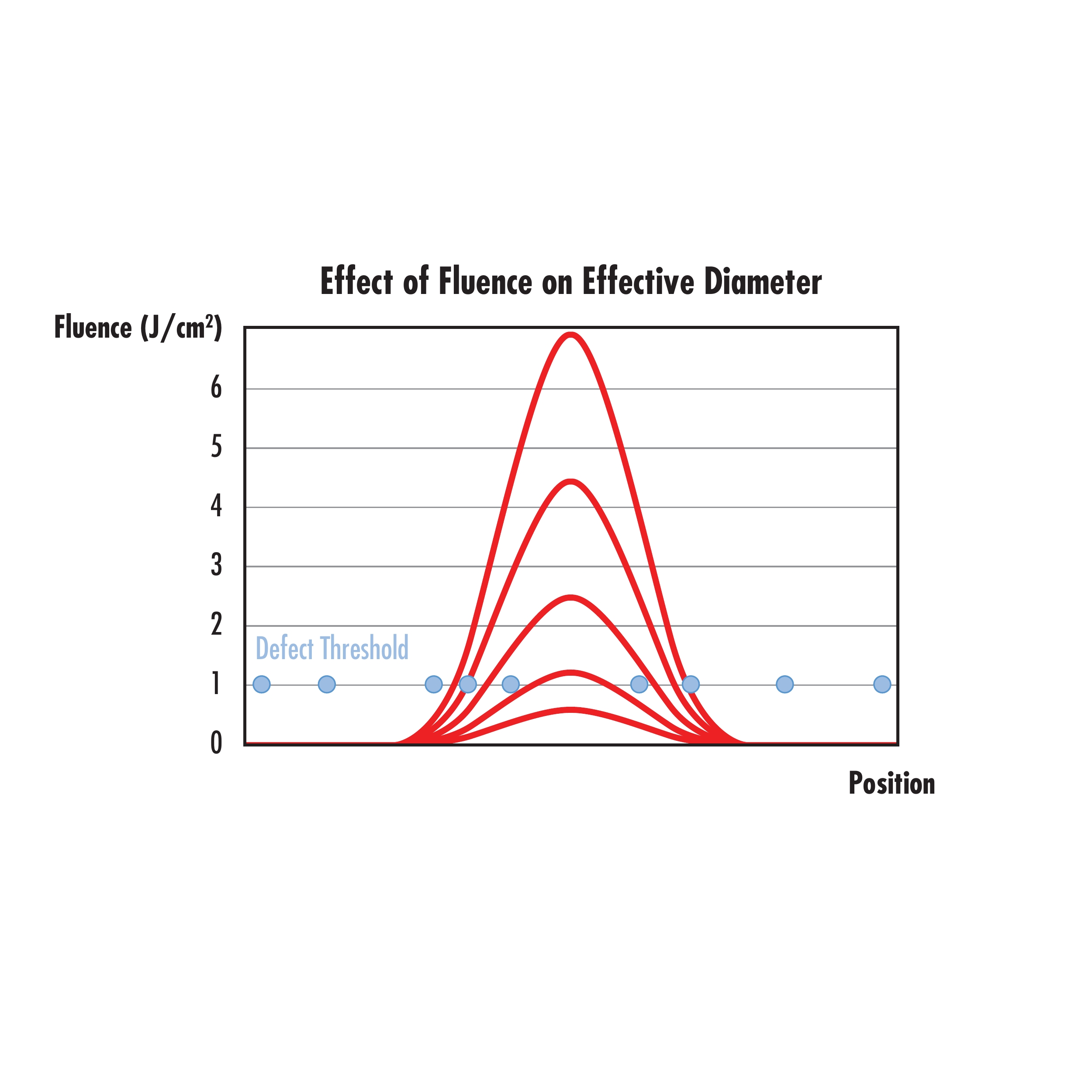
A Gaussian beam's effective beam diameter also scales with intensity. As intensity increases, a greater portion of the beam’s width has high enough fluence or power to cause laser-induced damage (Figure 3). Using a flat top beam can mitigate this effect, as a flat top beam's effective diameter remains constant through intensity changes.
A laser beam's intensity plays a critical role in determining the LDT needed for optics used in the laser system. Some lasers also suffer from unintentional regions of higher intensity throughout their beam profile called hot spots, which can contribute to more laser-induced damage.
Continuous Wave Vs. Pulsed Lasers
Continuous Wave (CW) Lasers
Laser-induced damage from CW lasers usually results from thermal effects caused by absorption in the optic’s coating or substrate.3 Optical components cemented together, like achromatic doublets, typically achieve lower CW damage thresholds as a result of absorption or scattering in the cement.
To understand an LDT specification for a CW laser, it is important to know the laser’s wavelength, beam diameter, power density, and intensity profile. CW LDT is often specified in units of power per area, such as W/cm2. For example, if a 5mW, 532nm Nd:YAG laser with a flat top beam is used with a beam diameter of 1mm, then the power density is:

Therefore, optics with an LDT specification lower than 0.64W/cm2 at 532nm, then the user is at a high risk of laser-induced damage. An extra factor of 2 would need to be added to the numerator of the equation above if using a Gaussian beam.
Pulsed Lasers
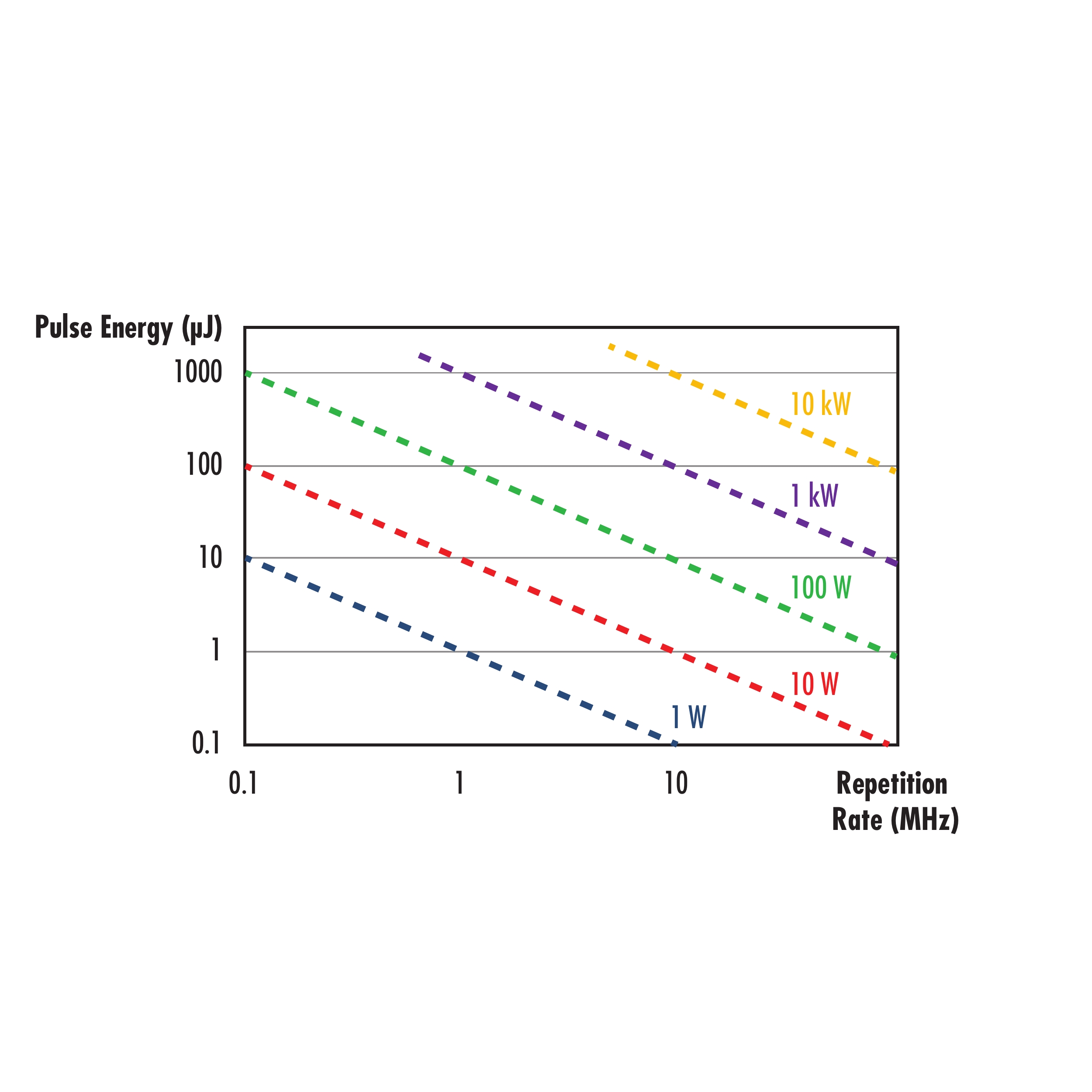
Pulsed lasers emit discrete pulses of laser radiation at a specified repetition rate or frequency (Figure 4). Energy per pulse is directly proportional to average power and inversely proportional to the laser's repetition rate (Figure 5).

Short nanosecond pulses typically cause damage through the dielectric breakdown of coating or substrate material caused by the high electric fields in the beam.3 Dielectric breakdown happens when current flows through an electrical insulator because the applied voltage exceeds the material’s breakdown voltage. For laser systems with long pulse widths or high repetition rates, laser-induced damage may be caused by a combination of thermal effects and dielectric breakdown. In this range, pulse duration is still on the order of the time duration of electron-lattice dynamics, which is responsible for thermal damage. However, these thermal processes become negligible for ultrashort pulses of about 10ps or less.4 In this case, nonlinear excitation of electrons from the valence band to the conduction band, because of mechanisms such as multiphoton absorption, multiphoton ionization, tunnel ionization, and avalanche ionization, causes damage.5

The LDT of pulsed lasers is described as a fluence instead of power density, typically with units of J/cm2. While the units J/cm2 does not contain a unit of time, pulsed damage threshold is significantly affected by pulse duration. For most situations, the LDT fluence value increases with increasing pulse duration. One cannot fully understand a pulsed LDT specification without knowing the laser’s pulse duration, repetition rate, wavelength, beam diameter, pulse energy, and intensity profile (such as Gaussian or flat top). The connection between a pulsed laser's fluence, pulse energy, and beam diameter is defined by:

For example, a Q-switched (pulsed) flat top laser with a pulse energy of 10mJ, pulse duration of 10ns, and beam diameter of 10 μm will have the following fluence:

A fluence in the range of kilojoules is extremely high and will most likely damage the optic, illustrating the importance of factoring in beam diameter in addition to LDT calculations.
Damage Mechanisms
Laser-induced damage can be also triggered by laser interaction with defects in addition to thermal buildup and dielectric breakdown. These defects include subsurface damage left behind from grinding and polishing processes, small particles of polishing abrasive left on the surface, or remains of metallic elements left behind from coating. Each of these defect types feature unique absorption characteristics and impact LDT differently.
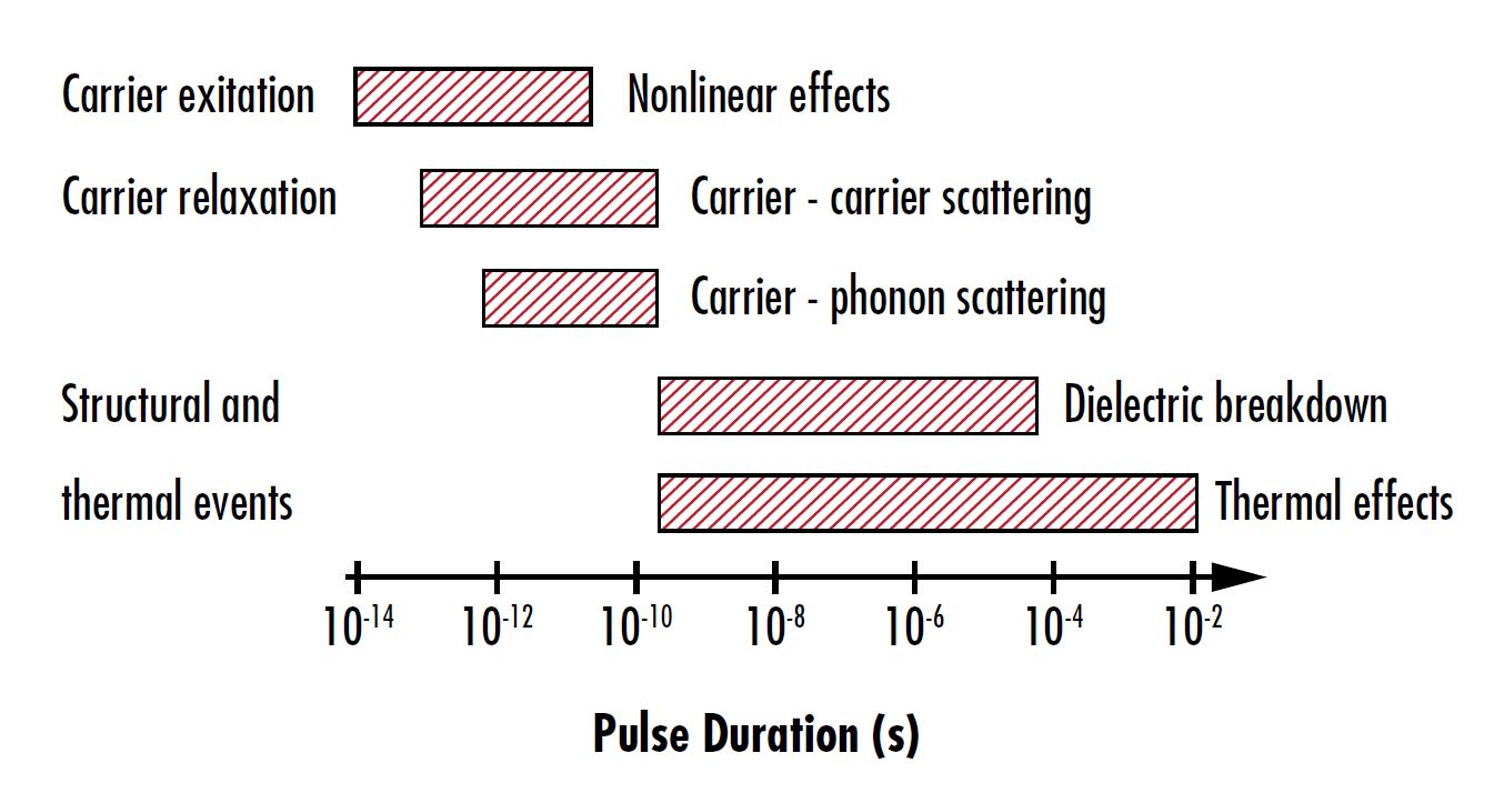
As mentioned earlier, pulse duration significantly impacts which damage mechanisms lead to laser-induced damage (Figure 6). Pulses on the order of femtoseconds - picoseconds can excite charge carriers from the valence band of a material to the conduction band, causing nonlinear effects such as multiphoton absorption, multiphoton ionization, tunnel ionization, and avalanche ionization (Table 1). Pulses on the order of picoseconds - nanoseconds may cause damage by relaxing charge carriers from the conduction band back down to the valence band through carrier-carrier scattering and carrier-phonon scattering.
|
Damage Mechanism |
Description |
|
Multiphoton Absorption |
Absorption process where two or more photons with energies lower than the material’s bandgap energy are absorbed simultaneously, making absorption no longer linearly proportional to intensity. |
|
Multiphoton Ionization |
Absorption of two or more photons whose combined energy leads to the photoionization of atoms in the material. |
|
Tunnel Ionization |
The strong electric field generated by ultra-short laser pulses allows electrons to “tunnel” through the potential barrier keeping the electrons bound to atoms, allowing them to escape. |
|
Avalanche Ionization |
The strong electric field generated by ultra-short laser pulses causes electrons to accelerate and collide with other atoms. This ionizes them and releases more electrons that continue to ionize other atoms. |
|
Carrier-Carrier Scattering |
Electrons accelerated by the electric field collide with other electrons, scattering them and causing them to collide with more electrons. |
|
Carrier-Phonon Scattering |
Electrons accelerated by the electric field excite phonons, or vibrations in the lattice of the material. |
|
Dielectric Breakdown |
A current flowing through an electrical insulator due to the applied voltage exceeding the material’s breakdown voltage. |
|
Thermal Effects |
Heat diffusion resulting from distortions and vibrations in the material caused by the energy of the laser pulses. |
Table 1: Descriptions of different damage mechanisms
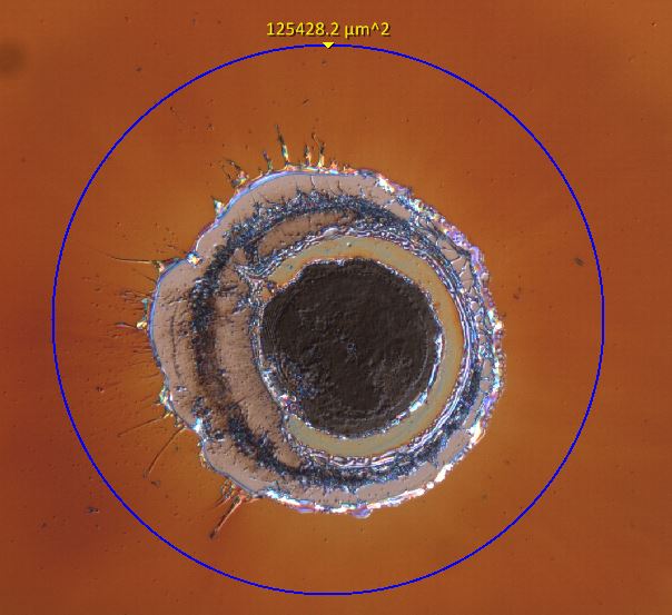
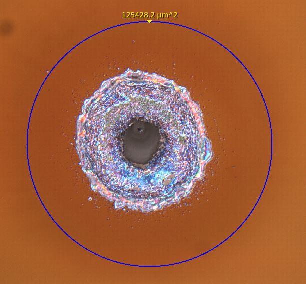
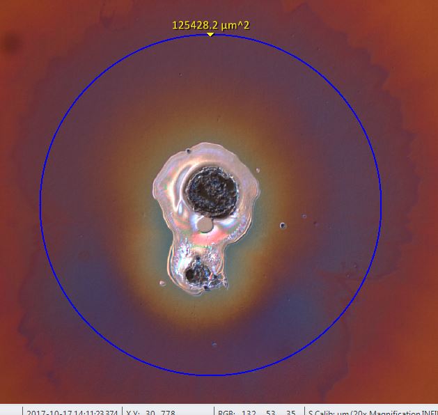
Varying root causes of damage lead to different morphologies of laser-induced damage (Figure 7). Understanding these different morphologies is important for developing coating and manufacturing processes. But for most laser optics system users, the morphology is only important in determining whether the damage significantly degrades the system’s performance past an application-dependent critical level. For example, in some situations a 10% reduction in transmission may be tolerable, while another more sensitive system may fail if more than 1% of the incident light is scattered. According to the ISO 21254:2011 standard, any detectable change in an optic after exposure to a laser is considered "damage."
  |
Scaling LDT
It is important to remember that LDT is highly dependent on wavelength and pulse duration. If an optic's specified LDT is at a different wavelength or pulse duration than that of the end application, the specification will not be accurate and must be evaluated at the real application conditions. Scaling a given LDT to different use conditions should be avoided when possible, because providing firm rules on scaling that are applicable to all situations is difficult. However, general rules exist for scaling a LDT value from the initial wavelength (λ1) and pulse duration (τ1) to a new wavelength (λ2) and pulse duration (τ2).7

This scaling should not be applied over large wavelength or pulse duration ranges. Some general rules of thumb for reasonable scaling ranges are ± 5% of input wavelength, ± factor of 3 of pulse duration, and ± factor of 2 of beam diameter. For example, Equation 5 would be adequate for a wavelength shift from 1064nm to 1030nm but should not be applied for scaling an LDT value at 1064nm to a drastically different wavelength, such as 355nm.
Laser damage threshold is one of the most important specifications to consider when putting together a laser system. Speak to your laser optics supplier for guidance in selecting the right components with a high enough LDT for your application without unnecessarily increasing costs by overspecifying.
References
- International Organization for Standardization. (2011). Lasers and laser-related equipment -- Test methods for laser-induced damage threshold -- Part 1: Definitions and general principles (ISO 21254-1:2011).
- R. M. Wood, Optics and Laser Tech. 29, 517, 1998.
- Paschotta, Rüdiger. Encyclopedia of Laser Physics and Technology, RP Photonics, October 2017, www.rp-photonics.com/encyclopedia.html.
- R. M. Wood, Optics and Laser Tech. 29, 517, 1998.
- Jing, X. et al., “Calculation of Femtosecond Pulse Laser-Induced Damage Threshold for Broadband Antireflective Microstructure Arrays.” Opt. Exp. 2009, 17, 24137.
- Mao, S. S. et al., “Dynamics of Femtosecond Laser Interactions with Dielectrics.” Appl. Phys. A 2004, 79, 1695.
- Mazur, Eric, and Rafael R Gattass. “Femtosecond Laser Micromachining in Transparent Materials.” Nature Photonics, vol. 2, 2008, pp. 219–225.
- Carr, C. W., et al. “Wavelength Dependence of Laser-Induced Damage: Determining the Damage Initiation Mechanisms.” Physical Review Letters, 91, 12, 2003.