High-Resolution Distributed Fiber Optic Sensing

Introduction
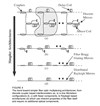
Fiber optic sensing has several key advantages over conventional sensing approaches. These advantages include lower cost and high reliability, and the sensors are electrically passive. High-performance fiber optic sensors are typically based on interferometric techniques that can detect extremely small changes in the phase of the light that has traveled through different paths. Fiber optic sensing technology is naturally evolving toward simpler transducers and optical architectures. Figure 4(a) shows notional optical architecture for a time-division multiplexed (TDM) sensor array using Michelson interferometers. Each sensor channel in the TDM architecture (shown in gray) requires three fiber optic couplers, two mirrors, an optical delay coil, and at least eight optical splices (not shown) to connect the individual components. Although the component costs are reasonable, the touch labor required to assemble each sensor increases the cost. In-line configurations, like that shown in Fig. 4(b), significantly reduce the component count and the required assembly time. In this configuration, the optical delay coil is merged with the sensor coil and each channel shares a mirror with the adjacent channel. While a significant improvement, touch labor is still required to make at least two optical splices per channel. Replacing the coupler-mirror components in Fig. 4(b) with fiber Bragg gratings (FBGs) further simplifies the architecture. The FBG, a wavelength-specific mirror, is written directly into the optical fiber and requires no external components or splices. With FBG mirrors, the architecture reduces to that shown in Fig. 4(c) in which the optical fiber in the system is a single continuous length of fiber. This allows automated manufacturing techniques to be applied, which significantly reduces the cost of the system. The next step in this evolution is to eliminate the FBGs and use inherent properties of the optical fiber to form the mirrors between the sensors, as shown in Fig. 4(d). This promises the lowest cost since no optical components are required and no special processes need to be applied to the fiber. In this architecture, the mirrors are "virtual" and can be formed anywhere in the fiber, allowing the array design to be dynamic with variable sensor location and aperture. This allows truly unique capabilities for an adaptive array that can be dynamically optimized to detect and track a particular target or reject a strong interfering signal.

Concept:
This vision can be realized by using the inherent backscattered signal in an optical fiber that results from random fluctuations in the index of refraction. This is the same principle used in optical time domain reflectometry (OTDR) in which the Rayleigh backscattered signal is examined for attenuation variations or breaks over a length of optical fiber. In our approach, instead of using the amplitude of the Rayleigh signal, we extract the phase information from the backscattered signal. The phase of the backscattered signal is extremely sensitive to path length variations, and length changes as small as 20 pico-meters can be detected with this approach. Depending on the aperture, this corresponds to strains in the 0.2 to 10 pico-strain range, which is an extremely sensitive strain sensor. Figure 5 shows a simplified block diagram using a receiving interferometer. Here, a pulse of light is passed through an optical circulator to interrogate a length of fiber. As the probe pulse travels through the sensing fiber, light is scattered back toward the circulator. The circulator routes this backscattered signal to a receiving interferometer with a path mismatch of ÄL between the two arms. The receiving interferometer delays the return signal by different amounts such that the backscattered light from two different sections of sensing fiber interfere at the output of the interferometer. The phase information from the backscattered signal can be extracted by monitoring the interference pattern. For each input pulse into the sensing fiber, the output of the receiving interferometer is a continuum of interference signals over a spatial aperture of ÄL/2. The physical location of the scattered signal is encoded in the time-of-flight of the return signal. Different locations in the sensing fiber can be monitored by selecting a different time slice in the return signal. For this configuration, the spatial aperture is set by the path difference in the receiving interferometer, which is fixed. It is relatively straightforward to reconfigure the electro-optics system to support a truly variable aperture on a pulse-to-pulse basis.

Results and Applications:
To demonstrate the sensitivity and spatial accuracy of this approach, a 180-m test fiber was interrogated. The test fiber contained three independently modulated 30-m segments, each separated by 10 m. Figure 6 shows the spectral output as a function of distance. The three 30-m sections are modulated at different frequencies, and the modulation on the third segment has been attenuated by 30 dB. These drive levels correspond to strains of ~200 nano-strain and 6 nano-strain, respectively.

We have applied this interrogation technique to a number of applications—from high-performance acoustic arrays to high-spatial-resolution structural monitoring applications. The unique capabilities of this interrogation approach make it very useful in many application areas.
We have recently applied this technology to the characterization and demodulation of coated fiber sensors. This is an enabling technology for coated fiber sensors systems that apply specialized coatings directly to the optical fiber to increase the coupling from the desired measurand to the optical fiber. Coated fiber sensors represent the lowest cost sensor technology in which a coating is simply extruded on a continuous piece of optical fiber.
The Rayleigh scattering approach has been demonstrated over several kilometers, and 10- to 20-km segments appear to be achievable. Long sensing lengths combined with the high strain and spatial resolution makes this an attractive and cost-effective sensing approach for many homeland security applications.
Sponsored by: ASTO and ONR
SOURCE: Naval Research Lab
