Hanks on Machine Vision: 10 Steps to Success with Vision Systems
By: John Hanks, <%=company%>
Contents
Why machine vision now?
Machine vision components
What comes next
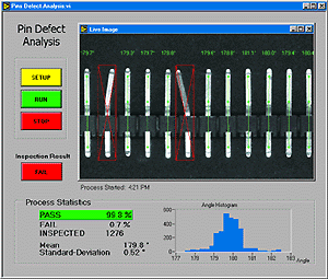
Vision machines are taking over in factory inspection. From inspecting automotive airbag sensors to culling blemished oranges from a packing line, to making sure drug capsules of the right color go into correctly labeled packages, vision machines are improving product quality and reducing production costs (see Figure 1).

Machine vision, the common name for the technology that joins unblinking cameras to a computer that analyzes what they see, is an important market segment of the photonics industry. Driven by converging technologies such us CPU advances, computer bus bandwidth improvements, and advances in machine vision algorithms, the machine vision market now makes low-cost PC-based vision systems a reality.
Raw PC processing power, easy-to-use software, and widely available information on systems integration mean that machine vision is not relegated to a handful of experts. Engineers and scientist with signal measurement and automation experience are now embracing vision is a standard automation and measurement tool. However, there are many considerations for new comers.
Why machine vision now?
Consider what's changed to enable PC-based machine vision to take hold in the industrial world. First, you can't ignore the remarkable performance gains of general-purpose computers from the standpoint of raw horsepower and bus-transfer rates. The well-known performance gains in the latest CPUs play a revolutionary role for machine vision. Higher clock speeds are only half the equation. Although originally intended for multimedia applications. Intel's MMX technology has proven to be a windfall for machine vision software. Because multimedia game applications and 8-bit images have much in common, a computer with the same clock speed that is MMX-enabled has as much as a 400% computational speed improvement. Many machine vision functions enjoy a significant performance gain for filtering, thresholding, arithmetic logical, and pattern matching operations.
It's important to realize, though, that performance gains for MMX imaging depend on the algorithm or function. For example, a histogram doesn't realize significant gains from the technology because this type of sorting routine can't take advantage of the MMX parallel architecture, which resembles the architecture of a fixed-point digital signal-processing (DSP) chip.
For the MMX architecture, one low-level computer instruction operates on as many as eight 8-bit data segments. Imaging processing benefits because a typical image acquired from a charged couple device (CCD) camera is an 8-bit image. Figure 2 shows the speed up of algorithms that are optimized for MMX. In the past, you needed special plug-in boards and to be able to program a DSP to achieve this level of performance. Today you can buy an off-the-shelf PC to get the performance.

The well-known computer bus transfer rate performance gains are also important. Transfer rates of earlier PCs limited their utility for machine vision applications, which require high throughput rates. As an example, consider a single data point in a vision application often consist of a 640x480-pixel frame, more than 300k 8-bit data points. The 16-bit ISA bus sustained data rate of 1.8M bytes/s isn't sufficient to handle the standard video rate of 30 frames/s. Today's computers with 32-bit PCI buses offer a potential of 132 M byte/s throughput to PC memory. Faster throughput means faster inspection times on the factory floor.
Machine vision components
Selecting components for a vision system can be overwhelming because of all the different components that are needed to meet your resolution and speed requirements. For resolution requirements, the choice of lens and camera effect the overall spatial resolution as well as pixel depth resolutions. In addition, the choice of frame grabber, camera, computer, and software ultimately determines the speed at which your inspection system runs. There are many choices and vendors for all of these components and the Internet makes it easier to compare functionality and make choices. Here is a high-level introduction to the components and some of the important features.
•Machine vision cameras
Analog monochrome video cameras predominate in machine vision applications. The ability to 'asynchronously trigger' a camera is a very important machine vision feature. An asynchronous trigger from a photocell or proximity switch allows you to acquire an image only when it comes into the field-of-view of the camera. The result is an image of the object under inspection that is nominally in the same position in the image. Many camera vendors such as Sony Electronics and Pulnix provide analog cameras with asynchronous trigger capabilities. These cameras are approximately $1000.
Digital cameras offer advantages over analog cameras but are typically more expensive. Digital cameras offer high-speed image capture up to thousands of frames per second, and they offer higher spatial resolution (there are cameras with 4000 x 4000-pixel CCD sensors available). Plus, they offer greater pixel depth with 12 and 14-bits of gray scale resolution. Dalsa, Kodak, Basler, and Hamamatsu offer ruggedized industrial digital cameras. These cameras typically range from $2000 to $1000.
• Illumination equipment
Another important aspect of machine vision is lighting. For monochrome applications, the objective is to separate the feature or part under examination from the surrounding background by as many gray levels as possible. The inability to separate the desired feature from the background complicates the development of inspection software, so you can see the importance of good lighting. Several vendors such as Schott-Fostec and Stocker & Yale offer industrial machine vision lighting equipment. The components range in price from a few hundreds of dollars to thousands dollars.
•Image acquisition
Before designing a vision system, you must evaluate image acquisition considerations to determine whether it is even possible to incorporate visual inspection to a manufacturing process. For example, you must investigate how fast the system must acquire an image. PCI-bus image acquisition boards for analog cameras typically keep up with 30 frames/s, which corresponds to a throughput rate of approximately 11 Mb/s. The inspection rate of the vision system is limited by either the camera's frame-output rate or the time needed for processing between acquired images. To improve performance, you can use a pair of cameras, vision cards, and PCs, where each setup handles every other part being inspected. This strategy doubles the processing bandwidth on the production line.
Another way to improve performance is to limit the image acquisition system's task by using a region of interest (ROI) feature, which is available on some imaging boards. An ROI can minimize the data being transferred across the PCI bus and then processed. Suppose that instead of acquiring a full-sized frame (640 x 480 pixels), it's adequate to work with an image size of 200 x 200; this step reduces the number of pixels from 307,200 to 40,000. Less data in the case 1/7th, yields faster results. Image acquisition hardware cost range from a few hundreds of dollars to thousands of dollars depending on features such as on board processing an acquisition rate. Vendors such as National Instruments and Matrox provide a wide range of image capture options.
• Software
When considering your first machine vision application, the software possibilities may appear to be overwhelming. There are so many slick algorithms from which to select that the questions you have to ask yourself are where do I start, and which algorithm is right for my application.
Often the quality of the software algorithm and ease of programming make the difference in the ability to develop an application. One algorithm often used in machine vision application that you should evaluate closely is pattern matching. Pattern matching is the process of finding a particular pattern (or grayscale feature) within an acquired image. The pattern (often referred to as a template or model) is compared to acquired images.
Because of the demands of the production environment such as unpredictable changes in illuminations and other process variations, good pattern matching software should be able to find a feature in many adverse conditions. The pattern-matching algorithm should locate a feature if it is rotated and scaled even in changing lighting conditions, when the camera is slightly out of focus, and when the object is partially hidden. The latest techniques classify the geometry or shape of the objects in the image and are fast and accurate.
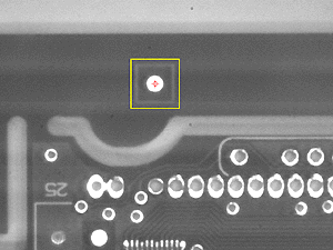
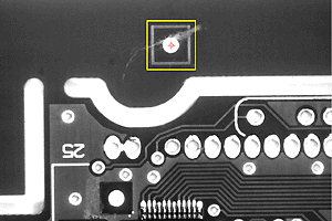
Figure 3 shows the template or model image of a fiducial on a printed circuit board (PCB) and how pattern matching locates the feature under various conditions. Knowing the location of more than one fiducial, the vision system can align the PCB, inspect components relative to their locations, and guide component placement. Pattern matching software can locate complex patterns in a full image (640 x 480) in less than 80 ms, and the objects can be at any orientation. For fast location, you can limit the search to find objects that are not rotated. In this mode, you can find objects as fast as 10 ms with a 100 x 100 template image.

• Motion control and other I/0
Often when an object moves down the production line, you need some way of knowing when the camera can see the object. You need to trigger an acquisition when the object is in the field of view of the camera and one way to accomplish this task is to use an inductive proximity switch or photocell. When the product is positioned correctly, an inductive loop or photocell drives a digital line to trigger the camera and the image acquisition hardware. Aromat/NAIS and Honeywell are two companies that offer a wide range of photoelectric and inductive proximity detectors for triggering image acquisition. These proximity switches output a TTL signal that can be input directly into an image acquisition board that has digital I/O capabilities.
Another consideration is how well the image acquisition hardware integrates with motion control and data acquisition hardware. If you are inspecting parts on a conveyor belt, you can use motion to control or monitor the speed of the belt as well as synchronize image acquisition. In addition, you may want to consider how to incorporate temperature, machine vibration, and pressure monitoring into your production system for predictive maintenance. Some image acquisition hardware offers synchronization capabilities with motion control and data acquisition hardware plus software to simplify integration.
What comes next
Now that you have an idea why machine vision is becoming so popular and an idea of some of the important components of a machine vision system, you may want more information. Future articles in the series will address important technical challenges in building a vision system and discuss important trends in the market. Each article will address one or more of these ten steps to success with machine vision:
- Step 1. Determining the inspection goals
- Step 2. Estimating the inspection time
- Step 3. Clearly identifying features and defects
- Step 4. Choosing a lighting and material handling technique
- Step 5. Selecting the optics
- Step 6. Picking the image acquisition hardware
- Step 7. Designing a software strategy
- Step 8. Integrating I/O and motion control
- Step 9. Calibrating and testing the inspection strategy
- Step 10. Developing an operator interface
About the author…
John Hanks is the Vision and Motion Control Product Manager at National Instruments. In his ten years with National Instruments he has worked for National Instruments in application engineering, marketing, and product management. He has also worked for Siemens Medical Systems Magnetic Resonance Imaging Division as an imaging support engineer. Degrees include engineering B.S. from Texas A&M and an engineering M.S. degree from the University of Texas. As a researcher at the University of Texas he studied image-processing algorithms and develop a system for biomedical cell counting. John has more than fifty published articles on signal processing, machine vision, and measurement technologies. He can be reached at National Instruments, 11500 North Mopac Expressway, Bldg. B, Austin, TX 78759. Tel: 512-683-011; fax: 512-683-5569; e-mail: John.hanks@ni.com.
