
EUV (13.5nm) Light Generation Using a Dense Plasma Focus Device, Part II: Scaling for Lithography
 Light Generation Using a Dense Plasma Focus Device, Part II: Scaling for Lithography")
ByWilliam Partlo, Igor Fomenkov, Cymer Inc., San Diego, CA
Daniel Birx, Applied Pulse Power Technologies Inc., Oakley, CA
Contents
We investigated a dense plasma focus (DPF) device as a light source for EUV lithography. This prototype DPF converts 25J of stored electrical energy per pulse into approximately 0.76J of in-band 13.5nm radiation emitted into 4p steradians. The pulse repetition rate performance of this device has been investigated up to its DC power supply limit of 200Hz with no significant reduction in EUV output. At 200Hz, the measured pulse-to-pulse energy stability was s=6% and we observed no drop out pulses. Part I of this article discussed the design and emissions of the DPF system. This part discusses scaling for lithography applications and outlines future work.
13.5nm Energy Measurements (back to top)
Calorimeters, vacuum photodiodes, and silicon photodiodes are typically used for absolute energy measurements in the EUV wavelength region. A silicon photodiode characterized the in-band energy per pulse generated by this prototype DPF.
Silicon-based photodiodes with EUV transmitting passiviation layers are now routinely available. The photodiode used for these measurements possesses a 60Å thick passivation layer of silicon dioxide with negligible absorption [1,2]. In the wavelength region of interest, these photodiodes exhibit a quantum efficiency given by (photon energy)/3.63eV. For the radiation centered at 13.5nm, the quantum efficiency is 25.2.
The first attempt to filter the incident radiation used a free-standing filter placed in front of a bare photodiode. Even with a silicon wire mesh, this filter--consisting of yttrium and silicon layers with 3500Å and 2500Å thickness respectively--was too fragile for practical use. The second attempt at filtering used a Ti/Y/C coating placed directly on the photodiode. The thicknesses of these layers were 60Å/2000Å/500Å respectively.
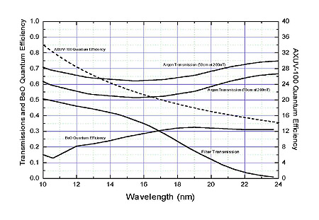
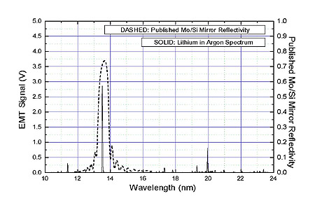
Since the transmission of the Ti/Y/C filter encompasses more than the 13.5nm lithium emission line, the measured lithium emission spectrum must be used to properly partition the photodiode signal according to the various emission lines. We must compensate for the wavelength dependence of the following: EMT quantum efficiency, grating reflection efficiency, argon transmission between DPF and the spectrometer entrance slit (50cm), argon transmission between DPF and the filtered photodiode (70cm), photodiode filter transmission, and photodiode quantum efficiency. The only factor in this list that is not known is the grating reflection efficiency. For these measurements, we assumed the grating reflectivity to be constant between 10nm and 24nm. The rest of these factors are shown in Fig. 1. Combining these factors with the measured lithium plasma emission of Fig. 2, we find that 69% of the charge generated by the photodiode is due to the 13.5nm emission line.
The Ti/Y/C filter also transmits hard x-rays. If this prototype DPF produces any hard x-ray photons, they will be heavily weighted by the photodiode because of the its high quantum efficiency for high energy photons. An uncoated photodiode located behind a 25µm thick beryllium foil generated no signal when the DPF was operated with lithium, thus demonstrating that no hard x-rays are produced under these conditions. However, hard x-rays can be detected through the beryllium foil when the DPF is operated with tungsten and a low buffer gas pressure (50mT).
Using the filtered photodiode, the calibrated in-band 13.5nm energy radiated from the DPF is 0.76J per pulse into 4p steradians. For this measurement the electrical energy initially stored on the C1 was 25J per pulse. Thus, the 13.5nm radiation represents 3% of the total electrical energy applied to the DPF.
Repetition Rate Scaling (back to top)
The proposed all-reflective EUV lithography tools are slit-scanning based systems. Because of the sliding window of the scanning exposure, any practical EUV light source must be capable of high repetition rate operation. Even with perfect pulse-to-pulse energy stability, a minimum of 10-20 pulses per sub-field are required to eliminate the dose errors associated with a pulsed exposure source and a continuously scanning exposure field. If the stability of the exposure source is less than perfect, then the necessary number of pulses per sub-field further increases.
State-of-the-art wafer stage scanning speeds are approaching 250mm/sec. The slit width of all-reflective EUV projection optical systems is expected to be smaller than corresponding DUV scanning systems. For example, the EUV LLC Engineering Test Stand has a designed slit width of 1.5mm as compared to the 5-8mm slit widths used on DUV scanning systems. To achieve a minimum 10 pulse exposure within each 1.5mm sub-field with a stage speed of 250mm, the source repetition rate must be 1,667Hz.
One promising feature of this DPF device is its proven high repetition rate capability when used as an electric plasma thruster for space applications [3-5]. Plasma thrusters routinely demonstrate short bursts of 3,000Hz operation. To investigate the repetition rate capability of this prototype DPF, we increased the repetition rate for short bursts while monitoring the EUV radiation output. There was no decrease in average EUV output up to the DC power supply-limited repetition rate of 200Hz. Fig. 3 shows the measured EUV output for a 0.25 sec burst at 200Hz. This burst represents an average EUV output of 152W radiated into 4p steradians.
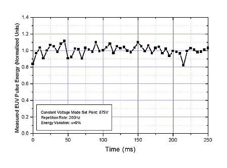
No significant burst transient occurred during these repetition rate measurements and no drop out pulses were observed. The pulse-to-pulse energy stability for the burst shown in Fig. 3 is s=6%. Improvements in energy stability beyond this present performance will be required to meet the needs of high throughput EUV lithography tools. In addition to the energy stability, the position stability of the DPF must meet a minimum set of requirements for a practical system.
Future Improvements (back to top)
The short burst repetition rate results of this prototype DPF in combination with the successful multi-kilohertz operation of plasma thrusters of similar design lead us to believe that 1000Hz operation of this DPF device as an EUV radiation source is possible. Continuous, high average power operation will be limited mainly by thermal loading on the central electrode.
The capacitance value used in this prototype DPF is larger than optimum. Figure 4 shows the measured voltage and current waveshapes for C1, along with the 13.5nm radiation intensity. Once avalanche breakdown occurs, the discharge current rapidly rises simultaneous with acceleration of the plasma sheath toward the end of the anode. The DPF occurs once the plasma sheath reaches the end of the anode.
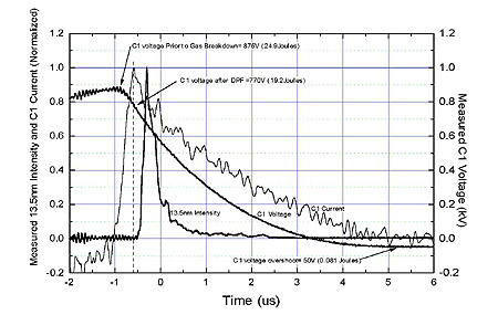
After applying the magnetically stored energy to the DPF (at t= -0.6µs in Fig. 4), the energy remaining in C1 contributes mainly to electrode erosion and heating and very little to 13.5nm output. From the waveshapes shown in Fig. 13, we can estimate that approximately 19J of the initial 25J stored on C1 has yet to leave C1 at the moment of DPF formation. This remaining 19J does eventually flow from C1 into the DPF device as seen by the nearly critically damped voltage waveshape. Only 0.081J of energy is recovered during the C1 voltage overshoot. The rest of the 25J initially stored in C1 is expended in the electrode region. An optimized (smaller) value of C1 would reduce the energy remaining on C1 after the termination of the DPF.
A second method of preventing excess energy deposition into the electrode region would be to implement a shunt element fabricated with saturable magnetics timed to short C1 to ground just after the DPF terminates. Such a shunt would redirect the remaining C1 energy away from the electrode region causing the C1 voltage waveshape to ring negative allowing the pulse-power system to recover this energy for use in the next pulse.
Under expected operating conditions, the DPF device will continuously produce vaporized lithium. Deposition of lithium atoms onto Mo/Si mirrors is expected to rapidly degrade mirror performance. A practical EUV lithography source based on the lithium DPF concept must employ a collector that is tolerant to lithium deposition.
Nested parabolic reflectors operating at grazing incidence represent a collection scheme that might be made tolerant to lithium deposition. A prototype optic of this type consists of 5 nested paraboloids each with a palladium coating on a nickel substrate. The optical design for this prototype is intended to collect and collimate a solid angle of 0.38 steradians. If 0.79J of 13.5nm radiation is emitted into 4p steradians, this prototype optic will collect 23mJ of in-band radiation per pulse. At a pulse repetition rate of 200Hz, the optic would collect an average in-band power of 4.6W.
Since this prototype optic is constructed entirely of high temperature materials, it will be possible to raise its temperature above the 180C melting point of lithium without damage or reduction in performance. Operating this optic at elevated temperature should continuously boil off the deposited lithium from the reflecting surfaces.
Surface finish degradation due to lithium impact is also a potential concern. The working distance for the prototype optic is 4.5cm while the mean free path of lithium in 200mT of argon is approximately 0.4mm. The lithium atoms should have no more than average thermal velocities upon contact with the optic's reflecting surfaces.
Conclusions (back to top)
Initial characterizations of this prototype DPF have shown that it can produce lithographically significant amounts of radiation with a spectrum well matched to the Mo/Si EUV mirror systems. The demonstrated 200Hz repetition rate exceeds that of most other prototype EUV light sources. Based on experience with this technology in electric plasma thrusters, we expect that multi-kilohertz operation is feasible. The demonstrated system efficiency of 3% is competitive with other source technologies and should further improve with the changes planned for this prototype machine.
The system geometry allows up to a 2p steradian collection solid angle. An optic based on grazing incidence parabolic reflectors is under investigation as a collection scheme tolerant to lithium vapor deposition. The relatively high EUV transmission of the argon buffer gas (91% through 10cm at 200mT) allows consideration of other debris mitigation methods such as foil traps [6].
Position stability of the DPF has yet to be carefully characterized. Initial results show that improvements in pulse-to-pulse position stability will be necessary to take full advantage of the 100-300µm source size. Energy stability is likely to be impacted by the same phenomena that effect position stability and thus efforts to improve these performance parameters will be of greatest importance.
Acknowledgements
The authors have made extensive use of the EUV transmission data made available by Lawrence Berkeley Labs and would like to thank those responsible. Guidance and feedback has been provided by Drs. Jeff Bokor and Bill Oldham and we would like to acknowledge their input to this project. We would also like to thank Kevin Duenow for his tireless efforts in assembly, maintenance, and repair of the equipment used in this research and Ken LaValley for his efforts in designing and detailing many of the components used in this prototype.
References
1. L. Canfield and J. Kerner, "Silicon Photodiodes Optimized for the EUV and Soft X-ray Regions," SPIE Proc. on X-ray and Gamma-Ray Instru. for Astronomy, Vol. 1344, pp 372-377, 1990. (back to article)
2. E. Gullikson, et. al., "Stable Silicon Photodiodes for Absolute Intensity Measurements in the VUV and Soft X-ray Regions," J. of Elec. Spect. and Related Phenomena, Vol. 80, pp 313-316, 1996. (back to article)
3. J. Ziemer, E. Cubbin, E. Choueiri, and D. Birx, "Performance Characterization of a High Efficiency Gas-Fed Pulsed Plasma Thruster," 33rd AIAA/ASME/SAE/ASEE Joint Propulsion Conference, Seattle, WA, 1997. (back to article)
4. J. Ziemer, E. Choueiri, and D. Birx, "Trends in Performance Improvements of a Gas-Fed Pulsed Plasma Thruster," 25th International Electric Propulsion Conference, Cleveland, OH, 1997. (back to article)
5. D. Birx, "Plasma Gun and Methods for the use Thereof," US Patent 5,866,871, Feb. 2, 1999. (back to article)
6. L Shmaenok, et. al., "Demonstration of a Foil Trap Technique to Eliminate Laser Plasma Atomic Debris and Small Particulates," SPIE Proc. on Emerging Lithographic Technologies II, Vol. 3331, pp 90-94, Feb., 1998. (back to article)