
EUV (13.5nm) Light Generation Using a Dense Plasma Focus Device, Part I: System Design and Emissions Spectrum
 Light Generation Using a Dense Plasma Focus Device, Part I: System Design and Emissions Spectrum")
By William Partlo, Igor Fomenkov, Cymer Inc., San Diego, CA
and
Daniel Birx, Applied Pulse Power Technologies Inc., Oakley, CA
Contents
We investigated a dense plasma focus (DPF) device as a light source for EUV lithography. Initial characterizations of a prototype DPF employing an all-solid-state pulse power drive found that substantial amounts of radiation within the reflectance band of Mo/Si mirrors can be generated using the 13.5nm emission line of doubly-ionized lithium. Part I of this article discusses the design and emissions of the DPF system. Part II discusses scaling for lithography applications and outlines future work.
A reliable, high brightness EUV light source with emission characteristics well matched to the reflection band of the Mo/Si or Mo/Be mirror systems is critical for practical implementation of EUV lithography. Since the proposed all-reflective EUV lithography tools are slit-scanning based systems, the light source must also exhibit high repetition rate capability. A practical EUV light source must operate debris-free or employ an effective debris mitigation strategy.
We investigated a DPF device as a source for EUV lithography because of its potential for high source brightness and high repetition rate operation. The prototype DPF, which employs an all-solid-state pulse power drive system, is based on the development work done toward an efficient electric plasma thruster for space applications [1-3].
Investigations of DPF devices as sources for proximity x-ray lithography [4-8] found that DPF systems could generate large amounts of radiation, but were limited in repetition rate due to large per pulse electrical energy requirements and short-lived internal components. The stored electrical energy requirements for these systems ranged from 1kJ to 100kJ. The repetition rates did not exceed a few pulses per second.
If the desired photon energy is reduced from the 1keV level required for proximity x-ray lithography down to 100eV, a scaled-down DPF device might achieve the desired EUV spectral power while consuming only moderate electrical power and operating at a high pulse repetition rate. Advances in all-solid-state pulse power technologies have made reliable multi-kilohertz electrical drive circuits a practical reality [9-11].
Dense Plasma Focus System (back to top)
A DPF device drives coaxial electrodes to a voltage potential difference at which a conductive plasma sheath forms between the inner and outer electrodes. Previous DPF systems operated with differences in the range of 10-50kV between electrodes, storing large energies in the drive capacitor. By employing magnetic pulse compression along with careful design of the drive inductance, this prototype DPF can operate below 1kV.
Fig. 1 shows a simplified diagram of the electrical drive circuit. The initial storage capacitor, C0, is charged on command by the DC power supply. Once full charge is reached, the IGBTs are triggered into conduction causing resonant transfer of energy from C0 to C1. In this prototype system, both capacitor values are equal at 65µF. Once peak voltage on C1 is nearly reached, a set of hollow cathode pre-ionization sources (not shown in Fig. 1) energizes, initiating avalanche breakdown in the gas between the inner and outer electrodes. The saturable reactor placed between C1 and the anode, holds off current flow from C1 until a uniform plasma sheath forms at the base of the electrode set.
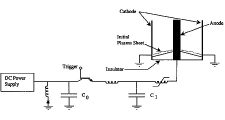
The low saturated inductance of this drive circuit ensures a rapid rise in current flow and allows the application of nearly all of the C1 voltage across the electrode set. Previous systems used spark gaps or thyratrons with no magnetic pulse compression. These systems suffered from much higher drive inductance and required higher voltage operation.
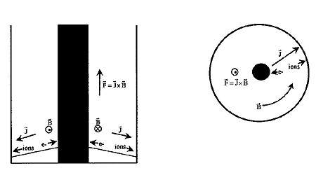
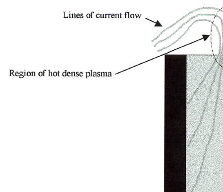
Once significant current begins to flow through the plasma sheath, J x B forces accelerate the plasma away from the base of the electrode set and toward the end of the anode. Figure 2 shows the flow of electrons and ions as well as the magnetic field and resulting force vector. As the plasma accelerates, the current flowing from C1 through the series combination of the drive inductance and electrode inductance rises toward a maximum. The plasma sheath is eventually driven off the end of the anode, causing magnetic forces to compress the gas in this region toward the central axis (Fig. 3). During this time, a fraction of the magnetic energy stored in the circuit inductance is transferred to the small region of compressed gas. Compression and heating raise the temperature of the ions in this region to levels sufficient for intense emission in the EUV spectral region.
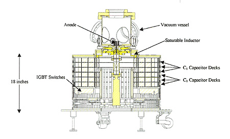
The C0 and C1 capacitors are each made up of 650 individual capacitors of 0.1µF with a 1400V rating. The large number of parallel capacitors reduces the inductance and equivalent series resistance of the capacitor decks to levels appropriate for matching to the plasma resistance. The IGBTs used to transfer the energy stored in C0 to C1 are the same as those used in the all-solid-state pulse power system currently employed in Cymer's excimer lasers. The eight IGBTs used in parallel each have a 1400V rating with an average current handling capability of 1000A.
The inductor and diode shown in Fig. 1 near the DC power supply are intended for energy recovery. If there is reflected energy due to overshoot of the C1 waveshape, a half cycle of LC ringing through this inductor and diode converts the resulting negative voltage on C0 to positive voltage [12]. Once this voltage conversion is complete, the recovered energy is available for use in the next pulse.
Spectral Measurements (back to top)
Mo/Si mirror systems exhibit high reflectivity only over a narrow band of wavelengths. Detailed measurements of the emission spectrum from this prototype DPF are needed to quantify the usable radiation.
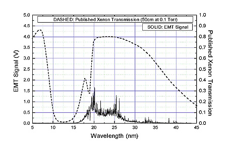
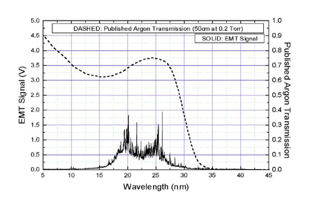
Initial characterizations used a solid tungsten anode and a buffer of 100mT of xenon gas. Figure 5 shows the measured spectrum for these conditions. Also included in this figure is the published transmission through 50cm of xenon at 100mT. Figure 6 shows the same measurement but with a buffer of 200mT of argon. The same broad spectral feature exists between 15nm and 30nm in both measurements, with minor changes most likely due to the differences in transmission between the two gases. The absorption feature in the xenon-buffered spectrum at 18.5nm matches the published xenon transmission data well [13].
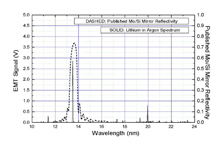
Placing a small amount of lithium on the tip of the anode changes the emission spectrum from predominately tungsten to that of lithium. Lithium has been proposed as an emission source for EUV lithography because of its narrow spectrum and intense emission into wavelengths well matched to the reflectance band of Mo/Si mirrors [14]. Figure 7 shows the emission spectrum of the DPF lithium plasma with 200mT of argon buffer gas over a range from 10nm to 24nm.
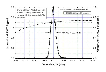
The 13.5nm lithium emission line matches well to the Mo/Si reflectance band. Figure 8 shows a finer resolution spectral scan centered on 13.5nm, along with the published reflectivity of a Mo/Si mirror. The measured bandwidth for this 13.5nm emission line is 0.03nm. This result may be spectrometer resolution-limited; the bandwidth of this emission line is likely less than 0.03nm. Fortunately, the exact bandwidth of this emission line is unimportant since even the measured 0.03nm result is much more narrow than the reflectance bandwidth of the Mo/Si mirror.
References
1. J. Ziemer, E. Cubbin, E. Choueiri, and D. Birx, "Performance Characterization of a High Efficiency Gas-Fed Pulsed Plasma Thruster," 33rd AIAA/ASME/SAE/ASEE Joint Propulsion Conference, Seattle, WA, 1997. (back to article)
2. J. Ziemer, E. Choueiri, and D. Birx, "Trends in Performance Improvements of a Gas-Fed Pulsed Plasma Thruster," 25th International Electric Propulsion Conference, Cleveland, OH, 1997. (back to article)
3. D. Birx, "Plasma Gun and Methods for the use Thereof," US Patent 5,866,871, Feb. 2, 1999. (back to article)
4. D. Nagel, "Plasma Sources for X-ray Lithography," VLSI Electonics: Microstructure Science, vol 7, pp 137-170, 1984. (back to article)
5. E. Cullman and T. Kunneth, "Comparison of Different X-ray Sources using the same Printing Process Parameters," J. Vac.. Sci. Tehcnol. B, 5 (3), pp 638-640, May/Jun, 1987. (back to article)
6. Y. Kato, et. al., "Plasma Focus X-ray Source for Lithography," J. Vac. Sci Technol. B, 6, (1), Jan/Feb, 1988. (back to article)
7. A. Heuberger, "X-ray Lithography," J. Vac. Sci. Technol. B, 6, (1) Jan/Feb, 1988. (back to article)
8. J. Eberle, et. al., "Plasma Focus as a Radiation Source for X-ray Lithography," Microelectronic Engineering, Vol. 3, pp 611-613, 1985. (back to article)
9. T. Watson, et. al., "Laser Having Improved Beam Quality and Reduced Operating Cost," U.S. Patent 5,748,656, May 5, 1998. (back to article)
10. D. Knowles, et. al., "Reliable, Modular, Production Quality Narrow Band KrF Excimer Laser," U.S. Patent Pending. (back to article)
11. D. Myers, et. al., "Production-Ready 2kHz KrF Excimer Laser for DUV Lithography," Proc. SPIE 3679, March, 1999. (back to article)
12. D. Birx, et. al., "Pulse Power Generating Circuit with Energy Recovery," U.S. Patent 5,729,562, Mar. 17, 1998. (back to article)
13. J. Blackburn, P. Carroll, J. Costello, and C. O'Sullican, J. Opt. Soc. Am., Vol 73, pp 1325, 1983. (back to article)
14. M. Klosner and W. Silfvast, "Feasibility of Various Discharge Configurations for High Intensity lithium Vapor Discharge Source at 13.5nm for EUVL," OSA TOPS on Extreme Ultraviolet Lithograph, Vol. 4, May, 1996. (back to article)