
Design Case Study: Fiber Optics Simplify Terahertz Imaging and Spectroscopy, Part II
By: J.V. Rudd, Picometrix Inc. and Colin Seaton, Coherent, Inc.
Contents
From lab to industry
System performance and imaging
Acknowledgement…
About the authors…
As discussed in Part I, T-rays (between 0.1 to 10 THz) languished for years in relative obscurity because terahertz radiation was so difficult to generate and detect. Terahertz time-domain spectroscopy (THz-TDS) uses a train of ephemeral, picosecond T-ray pulses to perform far-infrared spectroscopy. Each pulse contains just one cycle of terahertz radiation and is created by an even shorter pulse of laser radiation about 100 fs in duration.
From lab to industry
The commercial T-ray system consists of five main components beginning with a titanium-doped sapphire (Ti:sapphire) laser that delivers 200-mW, 100-fs pulses of tunable light between 750 and 850 nm at a pulse repetition rate of 80 MHz (see Figure 2).
Figure 2: Fiber-optic delivery of laser pulses makes
the T-ray system more compact, robust and flexible
for THz-TDS research. A separate set of Si lenses
focuses the T-ray to a diffraction-limited spot for imaging.
From the laser, the femtosecond pulses propagate free-space through a double-pass grating dispersion compensator (GDC), which conditions them for fiber-optic delivery by stretching them to about 5 ps. The negative group velocity dispersion (GVD) of the GDC makes up for the pulse-compressing positive GVD of the fiber optics that follow. The stretched laser pulses exit the GDC by coupling into a 780-nm-core singlemode fiber leading to the Picometrix control box.
Inside the control box, the fiber connects to a fiber box that splits and redirects the laser light in several ways. First, the light is split equally into pump and probe pulses, then the probe pulse is redirected from the fiber box through a free-space, variable optical delay rail and back to the fiber box. The delay rail consists of a 20-Hz rapid shaker (scanner) mounted on top of a slow-scan stepper-motor rail. The rapid shaker has a total delay excursion of 40 ps, while the slow-scan rail has a total delay excursion of 1 ns and a variable delay speed of 5 to 50 ps/s.
Before leaving the control box, 1% of the light is split off from the pump and probe pulses and directed to a photodiode for monitoring and control purposes. The control box also houses power and signal-conditioning electronics for the T-ray system.
From the control box, the pump and probe pulses travel through separate fiber-optic cables to the T-ray transmitter and receiver cases, respectively. Separate electrical cables handle the transmitter bias voltage as well as the receiver amplifier bias and signal current. The fiber-pigtailed modules housed within the transmitter and receiver cases measure just one inch long by half-an-inch square, are hermetically sealed using standard telecom packaging methods, and contain the optoelectronics for generating, directing, and receiving terahertz radiation (see Figure 3).
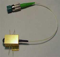
Figure 3: Central to the T-ray system are the fiber-pigtailed
transmitter and receiver modules, which are hermetically sealed
using standard telecom techniques.
The photoconductive antenna element inside each module is fabricated from low-temperature-grown gallium arsenide (LT-GaAs) and is permanently aligned to the fiber with sub-micron precision. An aplanatic, hyperhemispherical lens made of high-resistivity silicon (Si) and attached directly to the LT-GaAs collects the terahertz radiation efficiently and with little absorption or diffraction. Silicon collimating lenses 1.5 in. in diameter couple the T-rays out of the cases, which are purged with dry nitrogen to eliminate the strong T-ray absorption of water vapor. The receiver case also includes a signal amplifier for the T-ray signals.
System performance and imaging
The transmitter and receiver modules need just 1 mW of optical power each to function well. A transmitter bias of 24 V and a receiver amplifier gain of 500 are typical. Under these operating conditions, a 1-s signal-acquisition time—corresponding to 20 averages, or 20 delay scans of the rapid shaker—yields enough data to produce a SNR of 600:1, but a 5-min. signal-acquisition time (6,000 averages) produces a SNR of 10,000:1. Fourier analysis of the signal data produces useable bandwidth out to 2 THz for the 1-second average and beyond 3 THz for the 5-min. average.
A vital feature of this instrument is software control over the copious volume of data that it generates. Based on LabView, the software system has the look and feel of a standard Windows program and enables users to construct real-time terahertz waveforms as well as 2D images. Software control over the instrument is divided into four modes of operation:
- rapid scan
- long scan
- view scans
- image
The rapid scan mode allows the user to view data updates at a rate of 5 Hz, which permits real-time adjustments to the system and facilitates rapid setups for imaging. The rapid scan computer display shown in Figure 4, for example, illustrates a live, rapidly updated time-domain scan of the T-ray passing through a latex balloon (white trace) superimposed onto a stored background scan without the balloon (blue trace). The smaller graph depicts the frequency-domain Fourier transform of both traces. The horizontal slider bar above the graph corresponds to the rapid shaker's position on the long delay rail. Moving the slider enables the user to take a background scan at one delay point on the rail, and then analyze data taken at a different delay point for comparison.
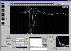
Figure 4: Computer-screen capture shows the Rapid Scan
software mode for real-time control of T-ray data
collection. Graphs can display time data, Fourier-transform
amplitude or phase, frequency absorptance, or a joint
time-frequency analysis (JTFA).
In the long scan mode, the operator simply enters the start, stop and scan-rate parameters, selects the desired number of averages, and clicks the Start Scan button. This mode of operation is useful for looking at complicated terahertz pulses that last for more than 40 ps, or when trying to resolve sharp resonances.
The view scans mode allows for the viewing of up to eight sets of stored data taken in either the long or rapid scan modes. In this mode one can look at many different plots in the time or frequency domains and spot differences that otherwise might not be obvious.
To collect 2-D images in the image mode, a separate set of Si lenses focuses the T-ray to a diffraction-limited spot and the object is scanned at up to 10 pixels per second by an XY translation stage controlled from the software. At each pixel the software stores the full terahertz waveform, which makes possible multiple image analyses on a single image data set without rescanning.
Automated software control over imaging and data-collection, fiber-optic beam delivery, hermetically sealed modules, and a compact design all contribute to a T-ray system that is both adaptable and easy to use. With almost two decades of useable bandwidth from 0.03 to 2 THz, this new instrument should help make the terahertz spectrum accessible to nearly everybody.
Acknowledgement…
Special thanks to Dave Zimdars and Matt Warmuth at Picometrix, Inc. for their contributions to the development of the T-ray system, and to the Air Force SBIR program and Program Manager J.R. Gord for partially funding our work.
About the authors…
J.V. Rudd is terahertz project leader at Picometrix Inc., PO Box 130243 Ann Arbor, MI 48113-0243. Phone: 734/998-4501; fax: 734/998-3474. Colin Seaton is business development and marketing manager at Coherent Inc. Laser Group, 5100 Patrick Henry Dr., Santa Clara, CA 95054. Phone: 408-764-4983; fax: 408-988-6838.