
Design Case Study: Dynamic Gain Flattening Improves EDFA Performance
By: James Regan, <%=company%>
Wavelength division multiplexing (WDM) is a key technology for increasing the capacity of fiber-optic telecommunications networks to meet the exploding bandwidth demands resulting from the rapid growth of the Internet. Until now, WDM networks have been essentially fixed, delivering a payload directly from one point in the network to another. Today, however, providers are beginning to deploy true optical networking where wavelengths are switched around the network for such applications as wavelength routing, protection, restoration, and bandwidth management.
The advent of optical networking is having a major impact on the design of optical components, such as erbium doped fiber amplifiers (EDFAs), that are used in WDM networks. The network is now more complex and the switching of wavelengths, whether done through electronic or optical cross-connects, creates dynamic power fluctuations that must be regulated with optical amplifiers.
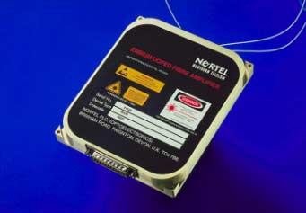
An intelligent Multiwavelength Gain Module (MGM) EDFA developed by Nortel Networks, Optoelectronics implements automatic gain control with amplifier spontaneous emission (ASE) correction to compensate for the noise created by the amplifier itself (see Figure 1). The smart, digital signal processing (DSP)-based MGM EDFA senses power levels and adjusts them within microseconds to prevent transient effects caused by the switching of wavelengths from impacting other wavelengths in the WDM system.
Gain control
Power fluctuations occur in WDM systems because the input power to the amplifier is the aggregate of all the wavelengths. For example, if four wavelengths are dropped in an eight-wavelength system, there is a 50% (3 dB) decrease in input power to the amplifier. What's more, the dynamic range seen by the amplifier increases with the number of wavelengths. Dropping 15 wavelengths in a 16-wavelength system, for example, would result in a 12 dB decrease in input power.
Input power is also affected by the length of the optical path, which can change as signals are rerouted along a different path in the network for the purpose of load balancing, switching protection, or new service deployment. Different path lengths result in varying degrees of attenuation, which affects the input power.
Traditionally, the output power of an amplifier in optical systems is fixed. Changes in the input power resulting from adding or dropping wavelengths will therefore change the gain—and hence the gain shape—produced by the amplifier. A change in gain shape can affect other wavelengths, in effect cross-coupling power variations in one wavelength onto other wavelengths.
To keep the gain spectrally flat as wavelengths are added or dropped, the output must be adjusted in line with the input to clamp the gain. This is done through a control loop that monitors the input and output powers, and adjusts the pump lasers to keep the gain constant (see Figure 2).
The situation is complicated, however, by the fact that the output power also includes ASE noise contributed by the amplifier itself. The ASE noise, which varies with the input power, must be subtracted by the control algorithm. Taking advantage of its DSP processing power, the MGM EDFA uses a complex control algorithm to achieve this goal (see Figure 3).
Transient events
While the gain control feedback circuit maintains the gain shape in steady-state conditions, problems still arise when wavelengths are switched in a system because a transient pulse can be transferred to another wavelength. Many transient events, such as switching or connector make/breaks, happen very quickly¾on the order of a millisecond or less. Traditional optical amplifier technology cannot handle these speeds.
Moreover, as these transient pulses propagate through the network, they speed up and build as they pass through multiple amplifiers. As a result, the signal can rise out of the receiver's dynamic range or fall into the optical noise, introducing bit errors on another wavelength. To prevent transient effects from impacting other wavelengths, optical amplifiers must be able to sense and respond to network changes very quickly.
The amplifier includes a dedicated DSP chip and control algorithm to achieve dynamic control of the EDFA (see Figure 4), as well as correct for the ASE noise discussed earlier. A microprocessor handles other functions such as communications and alarms.
Other approaches lack either the speed or the flexibility offered by this design. The control circuit could be constructed using analog electronics. While fast, these devices cannot easily compensate for the ASE noise and must be redesigned each time upgrades are made. The control circuit could also be microprocessor based, which while flexible and implemented in software, lacks the speed to deal with the transient effects.
Implementing the control function in software on a dedicated DSP chip provides several advantages. With software, the amplifier can evolve by introducing more sophisticated algorithms. Fresh software can also be downloaded onto the amplifier module to upgrade performance or functionality even after it is deployed in the network.
The flexibility afforded by this DSP-based software design also means the device can be tailored to provide different amplifier design variants to accommodate the parameters of different network applications and architectures and to optimize their performance.
In summary, this EDFA design approach provides the processing speeds to handle transient events in the network, the intelligence to compensate for ASE noise effects, and the flexibility to evolve to higher levels of performance and functionality in evolving WDM networks.
About the author…
James Regan is product line manager, amplifiers, Optoelectronics Division, Nortel Networks, Brixham Road, Paignton, Devon, UK TQ4 7BE. Phone: 01803 662325; fax: 01803 662801.