
Design Case Study: Digital light source solves CCD and LCD display test challenges
By Richard Austin, Gamma Scientific
Contents
System design
Testing CCDs
Display test
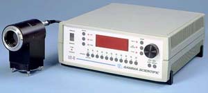
The photonics industry relies on the availability of precision light sources to develop, produce and test sensors, visual displays and other light sources in the visible, UV and infrared spectral regions. Obtaining a stable source that has a controlled variable output is difficult and relatively expensive. A new precision light source based on light emitting diode (LED) technology, precision analog electronics and micro-controller programming, offers a more economical solution than existing types of precision variable light sources and provides capability for computer interface beyond what is typically attainable (see Figure 1).
The RS-5 Digital Linear Light Source System is particularly useful for developing and producing charge coupled device (CCD) array sensors, independent of the readout technologies employed. In product inspection applications, for example, newer high-sensitivity charge-coupled device (CCD) detector line scan cameras designed to operate in lower light conditions can take advantage of lower-cost, LED-based illumination systems. In testing and quality control situations, the digital light source can match the exact spectral power distribution of the light source to be used in the final application, then provide a precision standard of irradiance (based on objective and repeatable criteria) to determine camera performance. Thus, the system can allow CCD manufacturers to avoid expensive rework and/or additions to field installations of CCD imaging base inspection systems.
Another application for this new precision light source is calibrating display measurement instrumentation. By combining three or more RS-5 light sources, each with a different wavelength distributed through the visible spectrum, engineers can create a precision light source tunable in both color and intensity. Careful selection of these wavelengths can yield a source that precisely models spectrally-complex light sources such as cathode ray tubes (CRT) and plasma or back-lit active matrix liquid crystal displays (AMLCDs).
The digital source provides a standard for calibrating display measurement instruments with lower uncertainty than standard broadband test sources, which, at best, can only provide intensity variation through the use of expensive, cumbersome, and relatively unreliable motor-driven mechanical shutters or iris arrangements attached to integrating spheres. Since the RS-5 source is based on digital electronic adjustment of intensity, it also provides manufacturers with precise display color rendering not only for each production run within a facility, but from one production facility to another—many of which are located oceans apart.
System design
The digital light source consists of two main components: a digital controller and an LED optical head. The system provides a controlled amount of light to a detector or device under test. The controller provides the user with both manual- and computer-control interfaces. These modes, selected with a front panel switch, allow the output power or output light intensity of the LED optical head to be adjusted to one part in 216, which translates to one part in 65,535. When the controller is set to activate the digital feedback control in the head, the linearity of the light output over this intensity range is better than 0.1% rms.
The source can operate in two calibrated modes of operation, one for radiometric values and one for photometric values (see Figure 2). Radiometric values can be defined in radiance or irradiance units, depending on the geometric configuration of the LED head—specifically, whether it has been coupled with diffusers to provide luminance or radiance (flux/unit area/unit solid angle), or a baffle tube for uniform field of illuminance or irradiance (flux/unit area).
The unit's controller also features storage of separate calibration constants for different LED heads, allowing it to run multiple heads, one at a time. The pulse duration without intensity reduction is limited to greater than 2 ms or a roll-off frequency of 500 kHz. The choice of light emitting diodes now covers the optical spectrum, from the ultraviolet through the visible region, with a wide choice of peak and dominant wavelengths into the near infrared, allowing users to tailor the system to their application.
Testing CCDs
The serial computer interface of the RS-5 can control the light output and log the effect of the change in intensity of the LED head against another measured parameter (see Figure 3). The system can, for example, characterize and monitor the performance of CCD detectors, CCD camera subassemblies, and CCD cameras. In this configuration, the host PC computer sets levels of the light source through the controller serial interface to provide a controlled amount of light to the CCD detector. The signal from the CCD is read into a computer, digitized and processed to determine performance metrics; the same computer also controls the amount of light delivered to the detector by the RS-5. This gives the customer trying to test detector performance closed loop control to permit fast, accurate, automated testing.
For example, the full frame can be digitized pixel-by-pixel, then the average of all the pixels computed. This process can be repeated until the full dynamic range of the CCD is evaluated. A simple baffle tube, rather than an expensive integrating sphere, allows the user to provide uniform illumination with less than 1% non-uniformity over the whole sensor area. Since the absolute flux density of the illumination at the CCD plane is known for each light-level setting, the gain linearity of the CCD and interface electronics can be saved to a disk file and plotted. Additional analysis on this pixel-to-pixel data will determine sensor performance parameters such as noise equivalent power, quantum efficiency and others.
Display test
In the process of characterizing display color and luminance, errors can be introduced by the difference between the spectral power distribution of the calibration light source and the spectral output of the display under test. To solve this problem, the RS-5 can be configured with multiple heads of different peak or dominant wavelengths, coupled into an integrating sphere. This configuration allows the unit to accurately calibrate color sensors, standard reference sources for LED manufacturers and users, and the performance of CCD sensors in different wavelength regions. Moreover, combining the spectral output of the multiple heads can generate a wide range of colors.
The first step in this process is to characterize the spectral power distribution of the each of the multiple heads to be combined into a tunable source. Consider, for example, the case of four LED heads configured on a 300-mm-diameter integrating sphere, allowing the user to generate any color within the chromaticity coordinate points of the four primary LED heads (see Figure 4).
The intensity of each primary LED can be precisely set independently, so the output color within the line segment bounds can be set to provide a calibration radiance standard for display measurement photometers and colorimeters. This standard helps compensate for the residual errors between the detector match and the true Commission Internationale de L'Eclarage, International Commission on Illumination (CIE) photometric and colorimetric response functions, in turn reducing the calibration uncertainty for measurement of displays with similar primary spectral power distributions. The reduction in measurement uncertainty is, of course, optimum for displays with the same primary illuminants, and backlighting of displays with LEDs is currently expanding to fill a larger percentage of these applications.
The integral digital control interface of the digital light source economically provides a solution to process control illumination requirements by facilitating computer automation of the whole test process. The digital control also assures stable and repeatable absolute output in conjunction with the inherent long life of LED lamps, providing a useful, robust testing tool.
About the author…
Richard Austin is president of Gamma Scientific, 8581 Aero Drive, San Diego, California 92123. Phone: 858-279-8034; fax: 858-576-9286; e-mail: gammasale@aol.com.