Vision Systems Guide Wafers Through Manufacturing Process

•Mapping and Handling
•Reading in Tough Environments
The semiconductor industry has become the largest user of automated vision systems – and for good reason. Cut from blocks of silicon, a wafer that will become hundreds of microchips starts as a finely machined disc some 200 mm in diameter. Before the disc is split into individual chips, the wafer undergoes dozens of steps – some of which are indiscernible by the human eye. If the wafer breaks the proper sequence of steps, it is lost and so are tens of thousands of dollars that it represents in lost revenue.
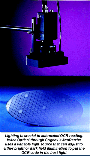
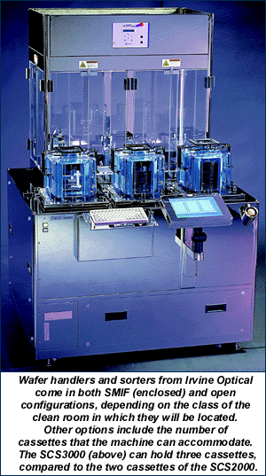
To track and protect the many high-tech process of semiconductor production, companies like Irvine Optical (Burbank, CA) sell sorting systems that use optical character recognition (OCR) to identify each wafer, sort it in a clean room environment and report the results to a central network (Figure 1).

Rather than become vision experts themselves, Irvine Optical put their trust in machine vision experts Cognex (Natick, MA) and their AcuReader – a compact single board system that can locate, identify and read OCR codes even when the code has been partially removed or occluded by deposition processes.
Wafer manufacture presents many challenges. Wafers are delicate, thin discs coated with many layers of special metals, each of which is less than the width of a human hair. A single speck of dust can corrupt this fragile surface, causing failure in the end product, and many of the manufacturing steps use materials that are hazardous to humans. Therefore, for most of their manufacture, wafers are passed through closed, vacuum-sealed machines in clean rooms with special filtration systems.
Special cassettes are used to store wafers between process steps and to allow transfer from one location to the next. In between each step, the wafer must be identified and its log updated as to what steps have been completed and what steps lie ahead.
Irvine Optical's SCS2000 can accommodate two cassettes inside its Class M1 mini-environment. "We use a dual PC system with one [133 Mhz Pentium] CPU dedicated to low level motion control and a more powerful user interface computer [300 Mhz] to deal with operator interfaces and OCR," explained Brian Patterson, applications engineering manager of Irvine Optical. (Figure 2)

The main internal computer uses the PCI bus to advantage by accommodating a 100 BaseT network interface card (NIC) for remote data access, a 6 GB hard drive for internal archival of images and logging of wafer numbers, and the Cognex AcuReader II card. Based on selection by a human operator or instructions from a control-host computer (across a central network), a sort recipe or program is executed which transfers wafers from one cassette to the next. The low-end CPU, which receives commands from the main computer, concentrates solely on robotic arm, servo and manipulator control. Several proprietary I/O cards attached to the motion control computer provide direction to the robotic arms.
According to Patterson, one of the most important draws of the SCS2000 is remote accessibility. "What we often find is that information is stored locally and most people will log on the tool from the outside at a remote location and retrieve those files. Driven clean-up can also be managed from remote locations.
"Overall, different fabs have different philosophies for the use of this tool. Some will rely solely on this tool to move wafers between cassettes, whereas others might use process tools to do that work. Sometimes they'll do a complete randomization of a cassette and in certain cases this helps with yield improvements. Others use the sorter with a stocker, which is a means of getting a lot of wafers from one area to another in the fab or storing [the wafers] while they're in process. Many times between the stocker to sorter we do some [OCR] verification or split some from a particular lot for later transfer to some other process step."
A crucial element to process control is the OCR code on each wafer. Newer manufacturing processes use soft marks, making the read even more difficult. "There's a big move away from hard scribing because manufacturers don't want to kick up a lot of debris," said John Petry, marketing manager with Cognex. "Soft marks just melt the material, changing the wafer's reflective properties to create the OCR code." On top of soft marks, many steps in the wafer manufacturing process entail depositing thin layers of metal or other material on top, further obscuring the OCR code.
To improve AcuReader's efficiency and reduce false reads or "unable to read" responses, Cognex uses a number of different methods, including an image formation system (IFS), traditional OCR through normalized correlation, built-in checksums and the company's own nonlinear OCR and virtual checksums.
IFS automatically adjust the internal lighting to best reveal the OCR code. Cognex offers two compact lighting configurations through its Aculight line for horizontal or vertical reading of wafers. The IFS function automatically adjusts the light intensity and switches between bright field (direct illumination) and dark field (indirect illumination) depending on which will result in the most successful read.
After adjusting the lighting, collecting an image of the wafer surface and identifying the wafer's notch or flat (a fiducial mark found on every wafer), AcuReader isolates the OCR code and compares it through normalized correlation against a stored library of industry standard fonts and formats. These fonts include the M13-88, M12-92, T2-93 and T1-93 standards developed by the industry association SEMI.
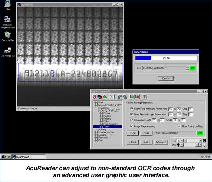
As designed by SEMI, these codes include a checksum at the end, or a few characters that represent the result of a function that uses the preceding code numbers. If the checksum matches the OCR code, then the wafer is positively identified. If the checksum is unreadable or the manufacture uses a code without a checksum, AcuReader compares the standard OCR read against the Nonlinear OCR read. (Figure 3)

Nonlinear OCR uses an edge-based algorithm to identify the OCR code. By comparing the code acquired through traditional and nonlinear OCR techniques, the AcuReader produces a virtual checksum. If this method fails because the code has been corrupted beyond set thresholds, then AcuReader notifies the User Interface computer to alert the operator, either through external alarms or by sending a signal through the Ethernet to the central network.
Presently, Irvine Optical uses the AcuReader II OCR reader. Processing is exclusively on-board through an AT&T DSP32C chip running at 80 MHz and another 40 MHz coprocessor. The latest version of the board, AcuReader III will get away from board processing and build on the processing power of today's Pentiums, shipping all image data to the motherboard for processing, Petry said.
According to Patterson, Irvine Optical intends to adopt the new AcuReader III OCR reading when semiconductor specific libraries and programming are completed.
