
Using Ion Sources To Improve Optical Thin Film Deposition
By Ron Willey, consultant, Willey Optical

As mentioned in my previous article [1], deposition processes are one of the key issues of optical coating fabrication. It was discussed that the energy of atoms during deposition was key to the resulting structure and properties of the films. In the processes where the materials are evaporated by heating, the evaporated atoms have very low energy, on the order of 0.1 electron volts (eV). Such atoms quickly lose their energy upon contact with the substrates unless the substrates are much hotter than room temperature (i.e. 250 to 300 degrees C). A typical way to add energy to the depositing layer is by using ion-assisted deposition (IAD). In this article, IAD source properties that can be used to improve optical film properties will be discussed.
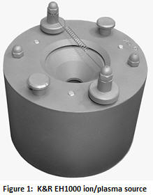
One typical ion/plasma source can be seen in Figure 1. This is a picture of a Kaufmann and Robinson (K&R) EH1000 source, and it is similar to the well known MK-II, originally from Commonwealth Scientific (now Veeco). Figure 2 is a sketch of the interior of an MK-II, but the principles of operation are the same for all of the sources described in this article. The gas to be ionized enters from below into an area of strong magnetic field. Electrons are “boiled” off of a heated tungsten cathode filament. They then travel upward to the substrate for neutralization, and downward into the throat of the anode to help ionize the gas (typically argon, oxygen, or a mix). The ionized gas is repelled upward by the high voltage anode. These ions will typically have an energy from 60 to 180 eV, and they bombard the depositing material forming the film. This energy adds significantly to that of the depositing atoms (compare 0.1 eV with 60 to 180 eV). Electrons from the cathode are also provided to neutralize the charge of the ions at the substrate.

The entire family of these “gridless” sources has similar behavior, and four were studied and compared [2]. It was found that their performance could be predicted by a simple equation. Figure 3 shows actual measured data points in drive volts (Vd, a measure of eV) on an MK-II as a function of gas flow in standard cubic centimeters per minute (SCCM). It also shows drive current (Ad) in a chamber with a pumping speed (PS) of 2500 liters per second. This is also a function of chamber PS, which is generally fixed in a given chamber.
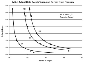
Figure 3: Measured data points on an MK-II
The curves that fit to these points are of the form of Equation 1:
Equation 1: Vd = Vbase +Smult/(SCCM –Soffset)
The Vbase term, which was found to be only a function of the PS, shifts the curve up and down to fit the data (as in Figure 3). The SCCM gives the reciprocal shape of the curve, and the Smult and Soffset terms adjust the shape to fit the data. The Smult and Soffset are functions of the Ad and PS, which vary with the particular source. Four sources were dealt with, including an MK-II, a K&R EH400, a K&R EH1000, and the DynaVac source (invented by the author, AKA “Fafnir”).
Tables 1 and 2 give the equations and coefficients which can be used in a spreadsheet to predict the Vd to be expected from any of these sources as a function of PS, SCCM, and Ad. Plots, such as those in Figures 4 and 5, can be generated. These show the similarities and differences between the MK-II and the K&R EH1000.
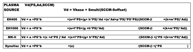
Table 1: Equations for each of the ion sources
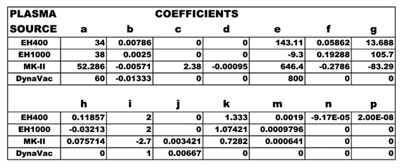
Table 2: Coefficients to use in spreadsheet for each source
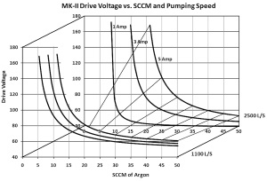
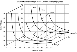
Figures 4 And 5: Plots from equations for an MK-II (left), and plots from equations for a K&R EH1000 (right)
Using An Ion/Plasma Source
As discussed elsewhere [3], a critical factor in getting the desired film improvement results from IAD is the ion-to-atom arrival rate (IAAR). Generally, this points to using the source at the maximum practical power to have the maximum ion arrival rate per second at the film. The material deposition arrival rate can then be adjusted to achieve the desired IAAR.
Sometimes, these sources are used in a pre-deposition phase to “clean” the substrates before coating, as in the typical glow-discharge cleaning process. This is not what is being discussed here. Such cases are typically done at IAARs that are 1/10 to 1/2 that of the IAD levels.
Source Operation
The control units supplied with the various sources mentioned may operate somewhat differently. What follows is a description of the operation if only manual controls are used.
The gas flow is turned on to the expected SCCM process level (or higher if necessary to get ignition). The control of the SCCM could be as simple as a needle valve when chamber pressure has been calibrated to SCCM. The cathode filament is then turned on and turned up to the process level or higher. The high voltage of the power supply is then turned on (in the current regulation mode), and the current is turned up until the plasma ignites. The plasma voltage (Vd) can then be adjusted by the gas flow at any given current (Ad) to achieve the desired voltage. If there is arcing or sparking in the chamber, the cathode/neutralizer current is turned up until the arcing stops. It is then adjusted lower until occasional arcing/sparking is seen in the chamber. Then, perhaps 5 percent more cathode current is added to avoid arcing during the process. The drive current (Ad) can be adjusted as desired, within the power limitations of the source. Some small adjustments may be needed in the SCCM and cathode current to return to the desired Vd.
The basics of these sources are that the gas flow controls the Vd and the cathode current controls the neutralization to avoid arcing.
Generally, the preferred eV of the IAD is as low as practical to minimize the dissociation of the atoms in the evaporating material compounds (i.e. the separation of Mg from F in MgF2, [4]). To keep the eV/Vd low, the gas flow is high, which causes higher chamber pressure. This high pressure is undesirable, since the gas molecules compete for position on the substrate with the depositing material and form less dense films. The balance of the eV with the pressure for the best film properties is a key process development task for each material process. The benefits of a proper IAD are great, but it requires greater attention to detail than a process not using IAD.
1. http://www.photonicsonline.com/doc/key-issues-of-optical-thin-film-coating-fabrication-0001
2. R. Willey, "Behavior of three types of plasma sources for optical coating," Society of Vacuum Coaters Annual Technical Conference Proceedings, 54 (2011).
3. R. Willey, Practical Production of Optical Thin Films, Second Edition, p276, Willey Optical, Consultants, Charlevoix, MI, 2012.
4. R. Willey, K. Patel, R. Kaneriya,"Improved Magnesium Fluoride Process by Ion-Assisted Deposition," Society of Vacuum Coaters Annual Technical Conference Proceedings, 53, 313-319 (2010).