
ReflectorCAD Simplifies Segmented Reflector Design
By: Jeff Miller, Breault Research Organization
Contents
Designing a reflector without reflector CAD
Designing a reflector with application-specific software CAD
Designing with application-specific software
Additional analysis
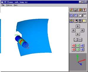
Segmented reflectors are useful optical components for many applications, including medical, automotive, architectural, and projection displays (see Figure 1). The components are not easy to develop with conventional optical design code, however. A new software package from Breault Research Organization, Inc. (BRO; Tucson, AZ), that can be used for any optical reflector system, simplifies the design of segmented reflectors, and eliminates repetitive prototyping.
An application-specific product, ReflectorCAD was designed from the ground up for use with segmented mirrors. The code automates the steps traditionally associated with designing a segmented reflector, and presents them in a logical, unambiguous framework, making it accessible to engineers with or without an optics background.
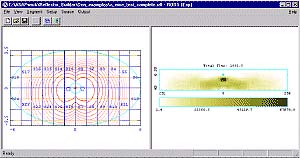
The main window for the application is divided into two sides—the left side is devoted to the design of the reflector, and the right half displays an isocandela plot (intensity) as a function of angle (see Figure 3).
Designing a reflector without reflector CAD
In segmented reflector development, the optical engineer is concerned with the following issues:
- starting volume
- light source
- reflector design
- simulation and test
- additional geometry
- prototype manufacturing
First, the designer must define the basic parameters of the problem. When designing a reflector using conventional tools, engineers use a base surface to define the starting volume or physical space limitation within which they must work. Finished reflector surfaces closely approximate the base surface. The designer must also define the light source, which, for the sake of simplicity, is generally specified as a light bulb. Finally, they must determine the desired output pattern or light distribution from the combined reflector and bulb. In automotive applications, for example, reflectors must comply with SAE requirements.
Once the basic parameters are defined, the actual task of designing the reflector takes place. Engineers design the reflector by dividing the base surface into separate, non-overlapping regions called segments. They then select the range of directions into which each of these segments should reflect light from the bulb. This step is known as aiming or developing segments.
After a prototype design has been developed, it must be tested to verify that it meets requirements. Output from the reflector/bulb combination is determined using a ray-trace application to see if it meets the requirements. If the design does not perform as specified, it goes back to the drawing board. Typically this is an iterative process continuing until the design meets the requirements.
When the optical design performs to specifications, non-optical pieces that are necessary to complete the design are added. A high-quality calculation of the output verifies that the complete design meets the requirements. If the design passes, the engineer exports the design for prototype fabrication.
A small number of companies have developed in-house tools to assist in this labor intensive error prone task. But it can be a large software development undertaking. So most companies have continued their course using hirer skilled optical or illumination engineers to perform the detailed task of segmented reflector design.
Designing a reflector with application-specific software CAD
Because ReflectorCAD was written for segmented reflector design, it contains modules that streamline the process. For example, the designer can define the base surface using a predefined bounded conic section, choosing the conic section curvature, width, and height, as well as the cutout for the bulb.
The software also permits users to import a base reflector, which gives flexibility in the starting point for the segments that are laid out. A base reflector can be designed in a CAD system, and output as an IGES file. Once the IGES file is imported into the Advanced Systems Analysis Program (ASAP) ray trace program (BRO; Tucson, AZ), where the MAP command is used to create a sampled surface. The sampled surface can be sent directly to ReflectorCAD and used as the base surface.
The software also details the starting light source using its own form of a source definition file (SDF file). The package includes an SDF file for each of the more than bulbs in the BRO Bulb Library. In addition, a separate utility program allows the user to create an SDF directly from any collection of rays generated in ASAP. This includes Radiant Sources (Radiant Imaging).
Designing with application-specific software
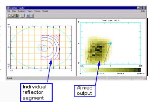
The real value of ReflectorCAD lies in the speed and ease of use offered in its simulated evaluation. To create a segment, the user simply points and clicks each corner of the segment (see Figure 4). Using the fast performance analysis engine, engineers aim the segment by dragging the corners of the output box. The software then orients the segment to achieve an approximate light distribution into the output box. When a segment's output is aimed on a Pentium class PC (300 MHz), it is virtually instantaneous.
Additional analysis
ReflectorCAD is a design tool that provides fast approximate analysis, it does not account for other characteristics that effect system performance such as surface roughness and variable reflectivity. It also does not model other mechanical structures that might be associated with the system design such as reflector top and bottom "shelves," source geometry, and additional mounting structures; for this reason the package includes useful export capabilities. After the initial design is complete, the user may translate the reflector segmentation geometry, including intersegment fillers, directly to a ray trace program for further detailed analysis, to an IGES file for use with a CAD package, or to other optical analysis programs that support the IGES format.
The software supports ASAP input files (INR file) and IGES files. Users can go directly from ReflectorCAD into ASAP or a CAD package to add system geometry, enabling further performance analysis.
To enhance usability, the package includes capability to create an IGES file of a design. This file can be used within a CAD program, or the IGES file can be sent directly to a plant for parts manufacture (see Figure 5). ReflectorCAD can also add the intersegment fillers, but be aware that these may not be manufacturable; typically, production mechanical engineers alter these intersegment fillers for moldability. These fillers do not affect the optical performance of a properly designed reflector.
About the author…
Jeff Miller is software development manager at Breault Research Organization, 6400 E. Grant Rd., Suite 350, Tucson, AZ 85715. Tel: 520-721-0500; fax: 520-721-9630; e-mail: info@breault.com; www.breault.com.