
OFC '00 Postdeadline: Automated Device Equalizes WDM Channels
By: Yvonne Carts-Powell
Using a Mach-Zehnder device with a filtering element in one arm, researchers equalized the power across multiple channels of a dense wavelength division multiplexing (WDM) system, developing a gain flattener that offers both broadband operation and sufficient resolution to individually alter up to 44 wavelengths. Chris Doerr and colleagues at <%=company%>' Bell Laboratories (Holmdel, NJ) reported on the work during the postdeadline paper sessions at the Optical Fiber Communications conference (OFC '00; Baltimore, March 5-10).1
The device consists of an integrated Mach-Zehnder interferometer with a grating-lens-grating cascade that can act as a filter in one arm (see Figure 1). The equalizer acts as an interferometer for each channel, using constructive or destructive interference to make the power output match that of the other channels. Those channels that don't require gain equalization are left alone, eliminating unnecessary attenuation. "When you don't need it," emphasizes Doerr, "you don't get filtering."
The optical signal from a WDM system enters the equalizer through a circulator, and is split into different polarizations. To minimize polarization dependent loss, (PDL), only light of a single polarization is directed through a polarization-maintaining fiber, and into a 11-cm-long integrated optical chip. The unfiltered arm of the interferometer incorporates a phase shifter, but no other elements. The wavelength channels are demultiplexed in the other arm, which contains two multi-waveguide gratings and a lens segment equipped with phase shifters. By adjusting the phase for each channel, the device uses interference to flatten the output power across all the channels.
Device design
The equalizer is made in silica waveguides on a silicon substrate, with a total chip size of 1.4 cm x 11 cm. Each lens waveguide, as well as the nonfiltered arm, is equipped with a thermo-optic phase shifter, consisting of a chrome heater over the waveguide. The phase shifters are spaced 100 µm apart, and controlled via heaters by 12-bit computer-controlled voltage drivers.
The group designed the chip with equal-straight and equal-bend lengths for the lens waveguides, so when none of the phase shifters are powered, the phase of light in each of the lens arms is well-aligned with the other. In other words, if the power is off, the device is transparent. It takes about 425 mW to induce a 180° phase shift with a shifter. When the two gratings are at the same temperature, they are wavelength aligned.
The overall electrical power consumption depends on flatness of the incoming signal, a relatively smooth profile can be equalized with about 5 W, but for more disordered signals the device draws up to 12 W. the researchers want to lower the maximum power to around 8.5 W.
The device exhibits an insertion loss of less than 6.8 dB over 32 nm, about 2.8 dB of which is from the circulator and polarization splitter used to insert single-polarization light into the equalizer. Thermal crosstalk is small.
Automating the equalizer
Doerr and coworkers wrote an automatic equalization program using an optical spectrum analyzer as a feedback source. First, the packaged device is calibrated and a file of values is built that includes the maximum transmissivity for all the controls (all the phase shifters) simultaneously, and the differences between the control and non-filtered electrical powers to obtain a maximum and minimum for each control point and its wavelength center. Then, when used as an equalizer, the system takes a scan from the OSA. The optical power in each wavelength band is adjusted by altering the power to the appropriate control (while making sure that the electrical power difference between that sent to the control and the electrical power sent to the nonfiltered arm of the interferometer stay within the limits found by the calibration).
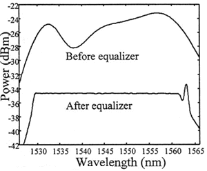
The group tested the program using an amplified spontaneous emission spectrum (see Figure 2). While the power is reduced, the resulting spectrum is flat between 1530 and 1560 nm.
The researchers also automatically equalized 40 laser peaks with an initial deviation of up to 9 dB. To make sure that the filter did not impair data transmission, on of the lasers was modulated at 10 Gbit/s, without noticeable penalty.
Reference
C. R. Doerr, et. al., "Automatic wavelength channel-by-channel equalizer" presented at OFC 00, Paper PD20.
About the author…
Yvonne Carts-Powell is a freelance science and technology writer based in Belmont, MA.